It all starts with some planning
The first question to answer is this: What will I power with solar electricity? At first glance that might seem like a rhetorical question. A normal response would be, "I want to power everything in my house." Well sure you do but here's the reality, "That's not going to happen with a battery bank off-grid system." For a more in depth look at why this is true, I go through some numbers in another post which clearly shows the reason why. With an on-grid system there's no problem, power everything you want.
My first whole house system I'll start with a very small list of things to power with it. The size of the system will be large enough to power these items, and will allow some room for adding more things to the list later. The main idea here is to build a Whole House System that I can experiment with to find out how much stuff I can operate on it. Yes, another experiment, although a much larger experiment this time!
That's a complete list for now. With less than 70 watts total load I should be able to see how well the sunshine keeps up with the demand for electricity. If all goes well keeping the batteries charged, there may be room to power more electric appliances later. We'll see...
My first whole house system I'll start with a very small list of things to power with it. The size of the system will be large enough to power these items, and will allow some room for adding more things to the list later. The main idea here is to build a Whole House System that I can experiment with to find out how much stuff I can operate on it. Yes, another experiment, although a much larger experiment this time!
- Living room lights, one 11 watt, one 18 watt 12 volt compact fluorescent lamp.
- TV set operating on 12 volt power brick, about 30 watts.
- TV antenna signal amplifier, about 2 watts.
- Telephone answering machine operating on 12 volt wall wart, about 5 watts.
That's a complete list for now. With less than 70 watts total load I should be able to see how well the sunshine keeps up with the demand for electricity. If all goes well keeping the batteries charged, there may be room to power more electric appliances later. We'll see...
How large is the Battery Bank
I'll have six 210 amp hour 12 volt batteries connected in parallel. Adding the amp hour ratings together we get 1,260 amp hours total. To find the recommended solar home maximum loading of a battery bank, divide 1,260 amp hours by 10 which gives us 126 amp hours. This number represents the most we can drain from the battery bank during the night. How much is that in kilowatt hours? 12.5 volts times 126 amp hours.
- Equivalent available power is 1,575 watt hours or about 1.5 kilowatt hours.
I chose this size because these batteries will "fit" in the space available inside my attached garage. That statement pretty much sums up the basis for the design - they will fit! But look, 1.5 kilowatt hours is a pretty good size to do a meaningful experiment and that's what I'm up to here, a meaningful experiment.
Battery Box placement
The Batteries will be in a very sturdy closed box against one wall inside the attached garage in my home. I built it using B-Line angle steel to support the weight of the batteries. Two batteries on each shelf, three shelves total. The front cover is removable for easy access to install batteries and do the wiring. There will be a circuit breaker box in the middle to protect the wiring to each battery. I decided to make the breakers accessible through an opening in the front cover for convenience.
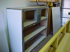
[ photo of battery box inside garage ]
I chose this spot because the temperature is moderated by the fact the garage is attached to the heated part of the house, and the garage itself is fully insulated. It's important to protect batteries from wide temperature variations, major heat in summer and freezing temperatures during winter months. Operating temperatures above about 95 F degrees or below 35 F degrees will shorten the life of lead acid batteries, and tend to reduce the capacity while still in service.
Balance Of System wiring
There is a lot of empty wall space for circuit breaker boxes, wiring boxes and Charge Controller adjacent to the battery box. I'm going to take advantage of this to keep wiring as short as possible to minimize voltage drop through the wires.
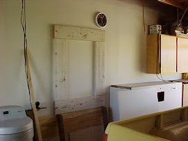
[ photo of wall space adjacent to battery box ]
A bare sheet rock wall isn't strong enough by itself to hold this kind of equipment. I used an electronic stud finder to locate the 2 by 4 studs behind the sheet rock. I attached some 2" x 8" boards directly to the wall studs with lag screw bolts. This rectangular area will be covered with a 3/4" sheet of plywood to be used as a base plate for mounting all of the electrical equipment boxes. Some of the electrical boxes are heavy and need a sturdy place on the wall to be mounted with lag screws.
A bare sheet rock wall isn't strong enough by itself to hold this kind of equipment. I used an electronic stud finder to locate the 2 by 4 studs behind the sheet rock. I attached some 2" x 8" boards directly to the wall studs with lag screw bolts. This rectangular area will be covered with a 3/4" sheet of plywood to be used as a base plate for mounting all of the electrical equipment boxes. Some of the electrical boxes are heavy and need a sturdy place on the wall to be mounted with lag screws.
Solar Panel array location
The route for wiring from the solar panel array in the back yard to the wiring boxes on the wall should be the shortest path possible. To make that happen the solar panel array will be placed in the back yard close to the garage back door.

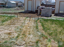
[ photo of solar array location ]
Here you can see the steel frame sitting on the ground in the approximate position where the solar panels are going to be mounted. The open door on the right is the garage entrance. Overall it's about a 60 foot run from the solar panels to the wall in the garage where the electrical boxes are located. As the bird fly's it's about 30 feet, but add in all the ups and downs and turns in the wiring path it gets longer. We need to keep the distance as short as possible to minimize power loss through the wiring.
Well that's the plan, so let's get to building.
Well that's the plan, so let's get to building.
The under ground trench for conduit runs
I'm going to orient the under ground conduit trench in such a way that the conduit will enter the house under the protective cover of the outdoor water bib. This will keep the PVC conduit protected from direct sunlight and keep it hidden from view for aesthetic reasons.
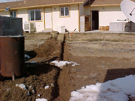
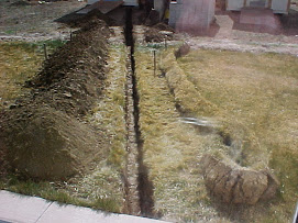
[ photo of trench looking toward the house ]
It's February 2005 when I start digging so the ground is frozen solid where you can see white going across the path of the trench. The trench goes under the concrete walkway next to the house and into the protected cover by the outdoor water bib.
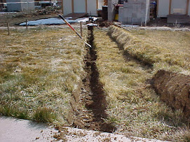
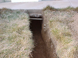
[ photo of trench looking away from house ]
In the other direction the trench continues beyond the solar panels and ends up at one of the backyard sheds in a single straight line path. Planning ahead was already under way long before I started digging the trench. The shed was built to house batteries, inverter, and all electrical boxes needed for a really big Whole House Solar System. After this "experiment" I'll have a better idea of how big of a system would be adequate to run the whole house all year long.
There will be two conduits in the trench: 1 1/2 inch conduit for DC current from the solar panel array for this project, 2 inch conduit for AC current from the big system within the shed for the next project. Laying both conduits into the ground now means I will only have to dig one trench - one time, instead of digging another trench later for the AC wiring.
There will be two conduits in the trench: 1 1/2 inch conduit for DC current from the solar panel array for this project, 2 inch conduit for AC current from the big system within the shed for the next project. Laying both conduits into the ground now means I will only have to dig one trench - one time, instead of digging another trench later for the AC wiring.
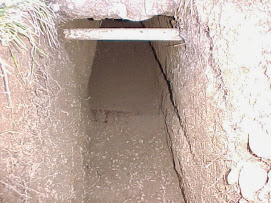
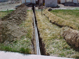
[ photo of completed trench looking away from house ]
It took a lot of hard work digging this by hand but here it is, mostly 4 feet deep the whole length. At this depth the conduit wiring is out of the way of any future back yard digging or tilling that may happen.
[ photo of trench under concrete walkway ]
Digging underneath existing concrete walkway was kind of interesting. I initially thought that it couldn't be done and thought about slicing a section out of the concrete. Instead I went ahead and started digging. I'm glad I did. It wasn't bad at all. In the picture you can see white plastic pipe used for irrigation just below the concrete of the walkway.
[ photo close up under walkway ]
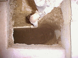
[ photo looking down from top of walkway ]
Here you can see some of the irrigation plumbing for the lawn sprinklers. The electrical conduit will lay beside this plastic water pipe.
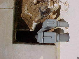
[ photo of electrical conduit in the trench ]
The smaller conduit is DC from the solar panel array and the larger conduit will carry the AC wiring in the next project. This is the point of entry into the house which is under the floor in the crawl space between two floor joists - just right.
[ photo of both conduits in the trench ]
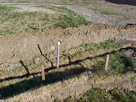
[ photo of where the solar panel conduit emerges from underground ]
The 1 1/2 inch conduit sticking straight up out of the ground here is the point where the solar panel array will be planted. The four wooden stakes in the picture is where the holes will be dug for mounting the framework for the solar panels to the ground.

[ photo of AC wiring conduit where it will attach to the shed ]
Now that all of the conduit is in place it's time to fill in the trench.
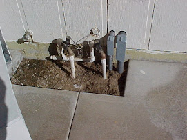
[ photo of what's inside the water bib cover ]
This is the point where the solar wiring enters the house under the protective cover of the water bib housing. Made out of 1/2 inch plywood and completely covered with galvanized steel sheet with soldered seams, it's quite heavy and will protect everything under it.

[ photo of trench during the fill in process ]

[ photo of "yard stick" by the conduit outside the shed ]
A standard 3-foot wooden yard stick is resting in the trench where the conduit emerges in front of the shed. Almost 3 feet deep here while some places it's almost 4 feet deep.
[ photo of trench all filled in ]
Done! The conduit is laid and ready for wiring, and the spot for the solar array is staked out.
In the next step I'll put together the Balance Of System, BOS as they call it in the solar industry. This includes things like wiring and circuit breaker boxes which will all be connected together with conduit. So let's move on to part 2.
Gregg Scholfield 10-25-2013
[ photo of trench under concrete walkway ]
Digging underneath existing concrete walkway was kind of interesting. I initially thought that it couldn't be done and thought about slicing a section out of the concrete. Instead I went ahead and started digging. I'm glad I did. It wasn't bad at all. In the picture you can see white plastic pipe used for irrigation just below the concrete of the walkway.
[ photo close up under walkway ]
[ photo looking down from top of walkway ]
Here you can see some of the irrigation plumbing for the lawn sprinklers. The electrical conduit will lay beside this plastic water pipe.
[ photo of electrical conduit in the trench ]
The smaller conduit is DC from the solar panel array and the larger conduit will carry the AC wiring in the next project. This is the point of entry into the house which is under the floor in the crawl space between two floor joists - just right.
[ photo of both conduits in the trench ]
[ photo of where the solar panel conduit emerges from underground ]
The 1 1/2 inch conduit sticking straight up out of the ground here is the point where the solar panel array will be planted. The four wooden stakes in the picture is where the holes will be dug for mounting the framework for the solar panels to the ground.
[ photo of AC wiring conduit where it will attach to the shed ]
Now that all of the conduit is in place it's time to fill in the trench.
[ photo of what's inside the water bib cover ]
This is the point where the solar wiring enters the house under the protective cover of the water bib housing. Made out of 1/2 inch plywood and completely covered with galvanized steel sheet with soldered seams, it's quite heavy and will protect everything under it.
[ photo of trench during the fill in process ]
[ photo of "yard stick" by the conduit outside the shed ]
A standard 3-foot wooden yard stick is resting in the trench where the conduit emerges in front of the shed. Almost 3 feet deep here while some places it's almost 4 feet deep.
[ photo of trench all filled in ]
Done! The conduit is laid and ready for wiring, and the spot for the solar array is staked out.
In the next step I'll put together the Balance Of System, BOS as they call it in the solar industry. This includes things like wiring and circuit breaker boxes which will all be connected together with conduit. So let's move on to part 2.
Photo Gallery
Gregg Scholfield 10-25-2013