Thursday, February 14, 2013

Broken Solar Panel, part 4

My Broken Solar Panel: Wiring it up to the batteries


To some this might seem like a lot of work for "just an experiment." You might be right, however, the tests we did with the solar panel so far indicate it will put out a reasonable amount of power. Having said that, I don't think all will be lost if we continue to make the installation look professional. The panel may end up being a long term work horse that is quite capable of performing very well. Time will tell of course.

Attach the solar panel to the frame


[ photo of panel bolted to frame with small B-Line bracket ]

This photo shows several things. Closeup is the little B-Line bracket bolted to the mounting frame and to the frame of the solar panel. The B-Line brackets were bolted to the mounting frame and positioned to the correct angle in part 2 when the frame was being built. I installed long bolts into the solar panel frame so they would stick out the back, you can see the extra nut against the solar panel frame. Then I carried the solar panel outside and hooked the protruding bolts onto the frame brackets. That way I didn't have to balance holding the panel while fussing to get a bolt started into a hole. I really try to make things easy for one person to install and work on.

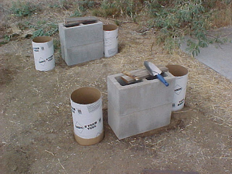
The other thing this photo shows are the galvanized pipe sections between the concrete and the base of the frame. I cut them from a 2 foot pipe I purchased at a local home improvement center. The pipe sections accomplish two things: 1-they give horizontal stability to the 3/8 inch threaded rods holding it in place, 2-each one is a slightly different length to precisely level the base of the frame. I tightened the nuts on the 3/8 inch rod fairly snug to compress the pipe sections between the frame and concrete. I tested the strength by pushing and pulling the frame sideways and found that it would not move. It should hold firm in any windstorm we might have.


[ photo of mounting at the base ]

Here you can see the slightly larger B-Line bracket attached to the base of the frame. I had to use a section of 2 1/4 x 1 1/2 inch B-Line to make this bracket so the bolt hole would reach the hole in the frame. With a little different perspective you can see how the galvanized pipe fits between the frame and concrete. I used a large "fender" washer on top of the frame to keep from bending the frame when the nut is tightened.


[ photo of solar panel installed ]

Here it is outside in the sunshine.

Wiring the panel to a disconnect / fuse box


[ photo of disconnect and fuse box attached to the frame ]

The wiring first goes to a disconnect switch box. This will allow me to work on wiring in the house safely by shutting off power coming from the solar panel. The disconnect box also has over current protection in the form of a fuse in case something should go wrong.


[ photo of solar panel wiring ]

Wiring from the solar panel itself isn't pretty because it doesn't have a junction box on the back. The two wires go into protective sheathing to protect them between the solar panel and the disconnect box. This is the same 12 gauge THWN wire that I used to rewire the solar panel to put out 60 volts.


[ photo of wiring to disconnect box ]

Extend the wiring to the house


The wiring exits the disconnect box through conduit which is buried in the ground for a short distance, about 10 feet. At that point the conduit emerges above ground again.


[ photo of conduit emerging above ground 10 feet behind solar panel ]


[ photo of conduit where it joins existing wiring in another conduit ]

Here the new wiring is merged with existing wiring. Part of the existing conduit wiring here is where the "old" 48 volt panels previously connected to the batteries. The old part has a new purpose and is not used with the broken solar panel.


[ photo of conduit installation painted to match house color ]

If I keep things looking nice the neighbors might not complain about "my experiments" in the yard.


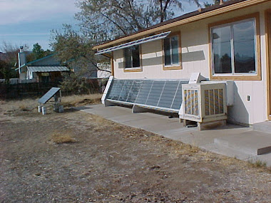
[ photo of broken solar panel with other solar things in my back yard ]

Inside the house


[ photo of junction control box ]

Here is where the solar panel connects to the batteries. There is a lot going on in this steel utility box.

  1. The terminal strip (lower right) solar panel wires are left most black/white pair. This is the main entrance. The other connections to the right are 48 volt DC outputs for appliances. A terminal block below that is where the battery bank connects, red/blue pair emerging from flexible conduit.
  2. Across the top of the box are fuses for inputs, outputs, monitoring and charge controller.
  3. The gray box (upper left) is the charge controller. It adjusts the amount of current going into the battery bank, depending on the state of charge of the batteries. It's reading 55.2 volts. The green LED (left) indicates "charging", LED (right) indicates battery in "good" condition.
  4. Black and red square box (lower left) monitors battery conditions such as amp hours taken out and put into the batteries, voltage, current in or out, and a number of other things. With this device you can tell the condition of the battery bank by reading just two items: voltage and amp hours.
  5. The top meter (right) reads amps from the solar panel, 1 amp full scale. I replaced this with a 5 amp full scale meter for the higher output of the broken solar panel. The bottom meter reads voltage, 100 volts full scale.

[ photo of 48 volt battery bank, 4 x 12 volt batteries wired in series ]

Batteries on the middle shelf comprise the 48 volt battery bank in this system. Four 12 volt 33 amp hour sealed lead acid batteries. The red/blue wires from each battery come together in a junction box in the middle where they are wired in series. The flexible conduit on the left side of the box is where the 48 volt wires connect to the control box in the previous photo. Each battery has its own in-line fuse for safety and disconnect. The clear plastic tube on each red/blue pair of wires coming from the battery is the fuse.

How is all this working?


The broken solar panel has been charging these batteries since 10-7-2012. The batteries are fully charged and even go into "float" mode on cloudy days. With the original 40 watts of solar panels that would not happen.

One day the battery bank was low because I had used it for charging my netbook and laptop computers and to run the wireless DSL router the previous evening. The next morning was cloudy and very little current was going into the batteries. When the sun finally peaked out from behind the clouds I saw 2.5 amps go into the battery bank at 54 volts, that's 135 watts! Not bad for a broken solar panel that almost went into a dumpster!

I have been using the 48 volt system to do a lot more at my work bench. I am very pleased with this. I would say the "experiment" is a success.

Photo Gallery


Gregg Scholfield    2-14-2013

Wednesday, February 13, 2013

Broken Solar Panel, part 3

My Broken Solar Panel: Mounting it to the ground

Making the 4 threaded rod attachments


The next step in the experiment with this broken solar panel is to mount it to the ground in my back yard so it can collect sunlight. I'll use threaded rod 3/8 inch diameter to attach the base of the frame to concrete posts. B-Line material of the frame has factory punched holes ready to accept bolts of this size.

Threaded rod is easily obtained at any local home improvement center. They usually have a good selection of various diameters and lengths. I chose 3/8 inch diameter by 3 feet long because it will be cut in half for this project, so I only need to buy two of them.


[ photo of frame with threaded rod installed ]

I'll start by attaching the threaded rods into the four corners of the frame. In the photo above you'll see there is a flat washer attached to the end with two nuts holding it secure. The purpose of the washer is so I can use the frame itself for marking the ground for digging the holes.


[ photo of 4 anchor brackets for the frame ]

After digging is finished, the washers will be replaced with the anchor brackets shown in the photo above. These brackets will be buried deep within the concrete resulting in a very secure bond and they will add some strength as well.


Set the frame in place to mark post holes


[ photo of frame in place for marking where to dig ]

This photo shows the frame sitting on top of cinder blocks in the location where it will be installed. There are small blocks of wood under each side to precisely level the frame. Leveling is important to get the correct angle to the sun.


[ photo of threaded rod marking the spot to dig ]

I used a metal stake to mark the ground where to dig. We'll move the frame out of the way when we're ready to start digging the holes.


And now we'll start digging the post holes


[ photo of fence post hole digger inside one of the holes ]

A fence post hole digger is really the best tool for making nice small round holes in the ground. Since we are installing a single solar panel the hole doesn't have to be very deep. The massive weight of the concrete will do most of the work holding the panel in place while the shallow holes will keep it from wandering.


[ photo of frame back in place ]

When the four holes in the ground are finished we'll set the frame back on top of the cinder blocks to check our work. If all went well the four legs will align with the four holes in the ground. If the legs don't line up with the holes we would have some problems to deal with.


[ photo left end of frame legs alignment with holes ]


[ photo right end of frame legs alignment with holes ]


[ photo right rear leg alignment with hole ]


[ photo close up of right rear leg ]

Install the anchor brackets on the legs


Now that the holes are finished and the alignment is checked we're OK for the next step, prepare the legs. Remove the washers we used for hole alignment and attach the anchor brackets to the threaded rod as shown here. The anchor brackets will extend almost to the bottom of the hole. This adds steel reinforcement to the concrete post and ensures the threaded rod will remain firmly in place.


[ photo of frame leg with anchor bracket installed ]


[ photo of two frame legs with anchor bracket installed ]

Prepare concrete forms for the legs


Concrete will fill the holes we dug for the legs but we'll need some concrete forms for above the ground. The base of the mounting frame will sit about 16 inches above ground. We'll use round tube concrete forms about 8 inches in diameter to do this. Home improvement centers have this type of material available in various sizes. I chose the smallest diameter they had, 8 inches, almost too big for this project.


[ photo of 8 inch diameter concrete form tube ]

One concrete form tube is 4 feet long. Instead of buying more of them to get 16 inches, we'll cut them into 12 inch lengths and make up the difference in height another way. We'll use a little less concrete because of this too.


[ photo of form tube after cut to length ]

I used a tape measure to mark one foot lengths around the diameter, then a battery operated circular saw to cut the cardboard tube. It is fairly thick material so a utility knife just won't do the job. For the next step a utility knife or scissors will clean up the ragged edges left by the circular saw.


[ photo of form tubes in place outside ]

Sometimes the best plans run into a snag and make you think, "why didn't I see that before?" In the photo above the form closest to the camera looks different than the others. That's because the length came up a little short due to a slope in the ground. Yeah, it's pretty subtle and I didn't see it until now.

To make all four tubes end at the same height below the solar panel mounting frame I had to extend the length of that one tube about 3 inches. I cut two strips from a heavy cardboard box and taped them to one end of the concrete form tube. Lots of 2 inch wide shipping tape! When concrete is poured into the form it will be very wet. Cardboard gets soggy when it gets wet. So, lots of tape...

And now let's pour the concrete


[ photo of concrete pouring tools ]

Here are the tools we need to pour concrete into the forms. The solar panel mounting frame is in place and leveled up. The legs are centered in the form tubes as best as possible. The form tubes are sitting straight up and down as possible. Ready for the concrete.

I'll use the small shovel in the foreground to transfer the concrete from the wheelbarrow into the form tubes. The straight copper tube with closed off end will be used to settle the concrete by tamping it down as the tube fills up. This has the effect of removing trapped air in the concrete which would otherwise leave empty spaces when it cures. The trowel will be used for the finishing touches on the top surface of the concrete to make it smooth to look nice.


[ photo of wheelbarrow and hoe ]

Mixing concrete one bag at a time is fairly easy with a garden hoe and a wheelbarrow. The garden hose in the previous photo is the water supply for this process. In the past I've tried measuring water in a bucket to mix concrete but it didn't seem to be the right consistency. Now I just spray the hose into the wheelbarrow, stir with the hoe, and repeat until it's just right. Somewhere between clumpy and runny is the sweet spot. If a clump from a shovel full can stand on its own with out flattening too much, that's the spot.


[ photo of first hole filled with concrete ]

We want to fill the hole a little at a time, then use the tamping pole to settle the concrete. A few more shovel fulls then tamp again. Yeah, you can probably tell there's a story behind this procedure. I didn't do this when I installed the big system that powers my home. And yes, there were air gaps in the poured concrete. Some of them appeared when I removed the cardboard form tubes after the concrete dried. Doesn't look very nice but it works OK.


[ photo of right end with bubble level ]


[ photo from rear showing all four concrete posts ]

Well that's it. Now we wait for the concrete to dry.

The next step is to mount the solar panel to the frame, wire it up, and attach it to the battery bank.

Gregg Scholfield    2-13-2013

Thursday, February 7, 2013

Broken Solar Panel, part 2

My Broken (Repaired) Solar Panel

In the previous post I made repairs to the broken panel making it safe[r] to handle. No, it's not completely safe with the exposed shattered pane of glass covering the front. It can still cut skin and clothing very easily if you brush up against it. The repair work keeps the panel from flexing when lifted and moving about.

Test Output Power before doing more work on the panel


Now that the solar panel can be moved around without pieces of glass falling off with every bump, we can move it into direct sunlight to test the Power Output. I verified the panel does put out 60 volts DC when sunlight shines on the solar cells. This confirms the rewiring job was done correctly because it used to measure 30 volts DC. Before I invest any more time and money into this broken 200 watt panel we need to find out if it is still capable of putting out some Real Power.

I attached some 12 gauge wires to the output terminals of the panel and connected the other ends to a DC motor I have. Purchased from a surplus sales company, it's a Lawn Boy lawn mower motor, rated at 36 volts operation. This will give me an indication if I can pull some amps out of the panel. So here goes, out into the sunlight. The motor spins! As I expose more of the panel to direct sunlight the motor spins faster and faster. Good!

A voltmeter is attached to the motor terminals and amp meter in series with one lead to monitor what is going on. So I move the panel further into the sun and the voltage goes to about 40 volts, pulling about 1.5 amps, that's 60 watts! Nice. OK, the test is done and was successful. Now it's time to get on with building a frame that can be attached to the ground outside.

Ground mounting design


My thoughts are to mount this panel to the ground using concrete poured into round holes dug into the ground, just like I did with the big system that powers my home. This will make the design of the metal frame fairly simple and it only needs to support one panel.

The base of the frame will be rectangular in shape to match the outline of the panel in landscape, long side parallel with the ground. Landscape mounting will give the concrete posts good spacing to attach the four legs of the frame to the ground. At my location on Planet Earth, the declination is about 39 degrees above the equator. So the panel will attach to the base frame and be secured at that angle.

Let's keep this simple to figure out how to build the frame and get the angle right. The work bench on which the solar panel is clamped is level, so that will be my reference. I used some B-Line metal bolted together at 90 degrees to be my "square". I'll hold it up to the back of the panel with the angle measuring tool held against one leg of the "square". When the angle tool points to 39 degrees I'll count the holes in the B-Line from the 90 degree corner to the edge of the panel. That will be the length for the Base leg. Then count the holes on the other leg of my "square" to find the length of the Back leg.

The tool is an Empire Polycast Magnetic Protractor. Its pointer uses gravity making it always point down to the calibrated scale marked in degrees. A Google search for empire magnetic polycast protractor will bring up lots of results so you can see what this tool is that I am using.


[ photo of basic framework sitting on solar panel ]

Here the Base leg is on the right side in the photo which is one end of the rectangular base of the frame. The width of the Base will be long enough to attach at about 6 inches in from each end on the solar panel.

To attach the mounting frame to the solar panel frame, I'll cut some short pieces of B-Line to make little 90 degree brackets. These will attach the frame to the solar panel at four points. You can see the short brackets resting against the back of the solar panel frame. Once everything was in place and squared up I marked the panel through the little brackets where I need to drill holes for mounting.


[ photo of long leg diagonal braces ]

The bottom of the frame is on the left in this photo. The two back legs are supported with diagonal brackets for stability. They held the frame rigid and square while I was positioning it for marking the drilling locations.

I may have gone overboard with the diagonal braces as the following photos show, but I don't want the wind to damage the panel or blow it away. That probably won't happen...


[ photo of diagonal brace view from outside frame ]


[ photo of diagonal brace view from inside frame ]


[ photo of diagonal brace view from rear attached to back leg ]


[ photo of diagonal brace view from rear attached to base ]

Yeah, that ought to hold...

To make all of those diagonal brackets fit as nicely as they do, I cut a notch out of each end just the right length. And on the correct side too! Here is how I made them start to finish:


[ photo of bracket before any cuts were made ]


[ photo of bracket with starting long notch ]


[ photo of bracket with finished long notch ]


[ photo of bracket with starting short notch ]


[ photo of bracket with finished short notch ]


[ photo of finished bracket with both ends filed smooth ]

In the above photo is one of the finished brackets, filed smooth where the cuts were made. You can see the pieces removed from it sitting on the back of the vice. This pretty much finishes up the frame to mount the solar panel.

The next step is to make the parts that will attach the frame to the concrete posts. To do that I'll use the same technique I used for the big system, long threaded rods buried inside the poured concrete posts. A threaded rod sticking out of concrete makes a very strong attachment point, and it's adjustable too. The threaded rod gives you plenty of room to make adjustments in height to level up the base of the frame.

Gregg Scholfield    2-7-2013

Tuesday, February 5, 2013

Broken Solar Panel, part 1

My broken solar panel: Repair it or dump it?


This all started out to be an upgrade to my current system.


I have four 175 watt panels in the back yard on a fixed ground mount that have been gathering sunshine for about 6 years. The system works perfectly well supplying power to the battery bank (1200 amp-hour total) but the cloudy days can severely limit electricity use in the home. With the recent drop in prices for solar panels I just couldn't resist buying some more. The 175 watt panels cost $995.00 each in 2005, these new 200 watt panels cost $180.00 each in 2012 when you purchase a whole pallet of them.

My boss and I went together and purchased a full pallet of 20 panels, 200 watts each. We divided it right down the middle, he gets 10 and I get 10. Perfect. Just what each of us wants to add to our existing systems.

The pallet arrives in good condition, we're both very happy about that. We pick off the top 10 panels and set them aside for him to take home when he gets a place set up to store them. The pallet of 10 remaining panels are loaded into the back of his full size pickup truck with a forklift. He's going to deliver them to my home, nice guy, because I have a small pickup truck and would require many trips.

We get to my place and unload each new solar panel into the shed that I have already prepared for them. All goes well until we get to the last panel resting on the pallet. When we lift it we hear a crunching, squeaking sound that none of the others made. We raise it up on its side and take a look at the front. Wow, what a pretty looking mosaic pattern in the glass. The two round white spots in each corner are where the panel rested on a plastic carrier intended to keep the panels separated and aligned with each other during transport. The white spots are where the glass breaking began and then spread to the entire panel. The plastic carriers were probably a bad idea for this purpose, ya think?


[ photo of broken glass on panel ]


Yes, it is completely shattered. The glass being Tempered broke into thousands of little odd shaped pieces. Because the glass is bonded to the solar cells with some kind of adhesive it is all still pretty much in one piece except for some tiny pieces that flake off the surface. Now what?

We notify the supplier of the problem and they graciously send a replacement to us (me). I am whole now but I have this broken 200 watt solar panel to deal with. What to do?

My boss said to dump it. Yeah, that would be the easy thing to do. I almost did dump it but they didn't want it in the dumpster at work. So I took it home with me.

What is the next step?


It sat outside in the weather while I pondered what to do with it. It even filled up with water during a spring rainstorm. All the while I considered this thing to be junk. So what the heck, I'll do some exploring and see how it is made. Maybe I can somehow remove the glass and salvage the solar cells. This is how it began...

I attempted to separate the broken glass from the solar cells below and found that I needed to get to the edge of the glass to get it started. To do that one side of the frame would have to come off. I removed the bottom of the frame by cutting through each corner with a hack saw, right through the seam at the 45 degree angle where the sides join. That frame is thick! 1/4 inch solid aluminum sandwiched between 16 gauge outer and inner framework.

I had to pull very hard to get the metal away from the glass/plastic solar panel sandwich because it is attached with double sided foam tape. Once off, the edge of the glass/plastic sandwich was at hand. I tried to force a utility knife into the junction between the glass and the backing. Progress with this method was slow and tedious. I was beginning to realize this may not be a good idea after all. So I tried using a heat gun to soften the adhesive and then pry the glass off with the knife. That did almost nothing to speed things along. OK, time for the propane torch. I heated a small section and picked off chunks of broken glass with the utility knife, but that wasn't any better either.

Stop. Rethink.


[ photo of damage I did to panel ]

Let me say that the adhesive used to bond the glass to the solar cells and plastic backing layer is some very sturdy stuff. I was only able to do some damage to about two square inches of the glass and one of the solar cells with my attempts at prying the glass apart. The glass is just not going to come off, period!

So ends the salvage operation...

Let's take apart the junction box on the back and see what's inside.


There are two wires coming out of the box, one is Positive and the other is Negative. New solar panels like this have the wires permanently attached, unlike the older ones which have a junction box with screw terminals for attaching your own wiring. The cover snapped off easily revealing a box filled with transparent rubber or something to keep water out of the electrical connections. I can see copper bus bars and other things through the transparent filler. It feels springy and soft. Maybe I can dig it out to reveal its secrets.

The transparent filler came out fairly easily although it took some time to get it all out of the way. There are copper ribbon straps which come from the solar cells that attach to rigid copper connections. The rigid copper sections are tied together with large surface mount diodes. These diodes are what keep the panel supplying power during partial shading of the panel surface. I was able to remove the two wires easily because they have standard ring terminals crimped on, and screws holding them onto the rigid copper.

I unsoldered the ribbon straps so I could use a volt meter to determine how the panel is wired. Here is what I found: There are 3 strings of cells, 10 volts per string, each string is actually 2 parallel strings of individual cells. So this is a 30 volt nominal output panel.


[ photo of junction box open ]

Thinking here for a minute -- if this was 60 volt output I could use this panel to upgrade my little 48 volt system. Maybe. More exploration of the wiring is in order.

Here is a photo of the panel near the junction box. You can see the area I scraped off using a chisel. The white covering scraped off easily, revealing the copper strap wiring underneath. This is starting to look like I may be able to do some wiring experiments. 60 volts output? Maybe!


[ photo near junction box ]


Repair the frame before going on.


Because this panel is starting to look promising to do some experiments with, it's time to put back the bottom of the frame that I removed earlier. So I carefully removed the double sticky tape from the channel in the frame and slid it back into place. It needs a bracket on each corner to hold it in place. I used two simple strap brackets from the hardware store. Bent them 90 degrees in the vice with a hammer. These already have 4 holes in an offset pattern which should work OK to hold the bottom of the frame in place.

I clamped the panel securely down to the top of the workbench. Held one of the modified strap brackets against one corner of the panel frame and marked where I need to drill holes to permanently attach it. After drilling the frame and attaching the bracket with two 1/4 inch bolts, I repeated the task on the other corner. Now the frame is back in place and appears to be fairly sturdy.


[ photo of frame corner with new bracket ]


Exploring the internals to find out how it's wired.


I scraped more and more of the white covering off. In the end I was able to draw a complete schematic of the solar panel showing all of the cells. The copper ribbons beneath the now clear backing material look like they can be cut using a rotary tool with a carving burr installed. Doing this would allow me to rewire it to get 60 volts output. This is the schematic of the panel as it comes from the factory.


[ original panel schematic ]

And here is the schematic with modifications to change the output voltage from 30 volts to 60 volts.


[ modified panel schematic ]

With this information in hand I'm ready to mark-up the back of the panel indicating where cuts should be made to the copper straps. Additional marks will identify the new jumper wire tie points.

Cutting the underlying copper straps went very well, so I used the same burr and cleared off a small area to solder the new jumper wire. That went well too so I cleared off all the areas where the new wiring will attach. A high power solder gun (325 watt) was used to 'tin' the cleared areas in preparation for attaching the wires.


[ photo of marked up panel ]

In the photo above the arrow is pointing to where the cut in the underlying copper strap will be. The two narrow vertical lines extending above the copper strap are the connections going to the solar cells themselves. These lines show where the cells attach and therefore where the copper strap needed to be cut to rewire the panel for a different voltage output. The new wiring is soldered to the copper strap at the label "J5+". To the right of the arrow you can see another cleared off area revealing bare copper before it is tinned with solder.

I used 12 ga THWN conduit wire for the new jumpers. Minimal voltage drop across the new wiring is why I chose to use this heave gauge wire. We want to minimize power lost in the wiring as much as possible.

Adding strength to the flimsy broken panel


Since it looks like I will be able to use this panel after all, or at least do more experimenting with it, the panel needs to be reinforced somehow. It bends and flexes easily now that the glass is broken into thousands of pieces and some of them are constantly flaking off. That's not good.

The panel is currently laying flat on its face on top of a work bench. The bench is very strong (2 1/4 inch laminated maple) and I know it is very flat. So I'll use this rigid base to keep the face flat and add the reinforcement to the back.


[ photo of panel clamped to workbench ]

The back of the panel is a fairly thick plastic with a white coating that I've been scraping off in places. If I use a good adhesive that will adhere to plastic and to galvanized steel then I can bond some angle steel to the back to hold it rigid and flat. The local home improvement center has some galvanized angle steel with large holes running the entire length which would be just what we need here. The holes in the steel will allow some of the adhesive to seep out around the openings resulting in more surface area for the adhesive to bond to.


[ photo showing adhesive on brackets ]

The galvanized angle steel was cut to length to span the width of the panel leaving about 1/4 inch on either end to allow for the wiring to pass by. 4 lengths were put into place evenly spaced. There was some material left over so I cut it into lengths short enough to fit between the longer ones, at 90 degrees to them. This will give a little more strength between the 4 long braces.


[ photo of braces on back of panel ]

Once everything was fit into place I marked the panel where they go. Applied adhesive to the galvanized steel and carefully placed the piece back onto the panel. I clamped all the reinforcements securely in place so the adhesive would dry with a good coupling between the panel and galvanized steel. I let it sit like this for a week. Not necessary to do it that long but this is a weekend project. I'll continue next weekend.

The braces themselves would hold the center portion of the panel stable but the outer perimeter where the frame attaches would still be flexible due to the broken glass, so more needs to be done here.


[ photo of bracket connecting brace to frame ]

The final step with the new braces in place is to secure them to the main framework. I used some left over pieces that were trimmed from the shorter braces, just a single hole in length, to attach the brace to the frame. I used 5/16" x 1/2" bolts with lock washer to make the attachment. One is installed at each end of the long braces, making 8 total. Now the panel is held in place with the braces on the back and the original frame holds it at the perimeter.

This should be strong enough to withstand wind and weather outside as well as all the handling necessary to get it installed. And this completes the salvage and modification phase of the panel itself. Next I will build a mounting framework for the panel so it can be placed outside tilted up toward the sun. If all goes well it should collect energy from the sun to charge the 48 volt battery bank, but this is after all just an experiment.

Gregg Scholfield    2-4-2013