Friday, October 25, 2013

Off-Grid Solar Electricity, part 1

It all starts with some planning


The first question to answer is this: What will I power with solar electricity? At first glance that might seem like a rhetorical question. A normal response would be, "I want to power everything in my house." Well sure you do but here's the reality, "That's not going to happen with a battery bank off-grid system." For a more in depth look at why this is true, I go through some numbers in another post which clearly shows the reason why. With an on-grid system there's no problem, power everything you want.

My first whole house system I'll start with a very small list of things to power with it. The size of the system will be large enough to power these items, and will allow some room for adding more things to the list later. The main idea here is to build a Whole House System that I can experiment with to find out how much stuff I can operate on it. Yes, another experiment, although a much larger experiment this time!


  1. Living room lights, one 11 watt, one 18 watt 12 volt compact fluorescent lamp.
  2. TV set operating on 12 volt power brick, about 30 watts.
  3. TV antenna signal amplifier, about 2 watts.
  4. Telephone answering machine operating on 12 volt wall wart, about 5 watts.


That's a complete list for now. With less than 70 watts total load I should be able to see how well the sunshine keeps up with the demand for electricity. If all goes well keeping the batteries charged, there may be room to power more electric appliances later. We'll see...

How large is the Battery Bank


I'll have six 210 amp hour 12 volt batteries connected in parallel. Adding the amp hour ratings together we get 1,260 amp hours total. To find the recommended solar home maximum loading of a battery bank, divide 1,260 amp hours by 10 which gives us 126 amp hours. This number represents the most we can drain from the battery bank during the night. How much is that in kilowatt hours? 12.5 volts times 126 amp hours.

  • Equivalent available power is 1,575 watt hours or about 1.5 kilowatt hours.

That's pretty small. Consider an average home like mine consumes about 25 kilowatt hours per day. So what use is this tiny amount of solar power going to be good for? Wait and see...

I chose this size because these batteries will "fit" in the space available inside my attached garage. That statement pretty much sums up the basis for the design - they will fit! But look, 1.5 kilowatt hours is a pretty good size to do a meaningful experiment and that's what I'm up to here, a meaningful experiment.

Battery Box placement


The Batteries will be in a very sturdy closed box against one wall inside the attached garage in my home. I built it using B-Line angle steel to support the weight of the batteries. Two batteries on each shelf, three shelves total. The front cover is removable for easy access to install batteries and do the wiring. There will be a circuit breaker box in the middle to protect the wiring to each battery. I decided to make the breakers accessible through an opening in the front cover for convenience.


[ photo of battery box inside garage ]

I chose this spot because the temperature is moderated by the fact the garage is attached to the heated part of the house, and the garage itself is fully insulated. It's important to protect batteries from wide temperature variations, major heat in summer and freezing temperatures during winter months. Operating temperatures above about 95 F degrees or below 35 F degrees will shorten the life of lead acid batteries, and tend to reduce the capacity while still in service.

Balance Of System wiring


There is a lot of empty wall space for circuit breaker boxes, wiring boxes and Charge Controller adjacent to the battery box. I'm going to take advantage of this to keep wiring as short as possible to minimize voltage drop through the wires.


[ photo of wall space adjacent to battery box ]

A bare sheet rock wall isn't strong enough by itself to hold this kind of equipment. I used an electronic stud finder to locate the 2 by 4 studs behind the sheet rock. I attached some 2" x 8" boards directly to the wall studs with lag screw bolts. This rectangular area will be covered with a 3/4" sheet of plywood to be used as a base plate for mounting all of the electrical equipment boxes. Some of the electrical boxes are heavy and need a sturdy place on the wall to be mounted with lag screws.

Solar Panel array location


The route for wiring from the solar panel array in the back yard to the wiring boxes on the wall should be the shortest path possible. To make that happen the solar panel array will be placed in the back yard close to the garage back door.


[ photo of solar array location ]

Here you can see the steel frame sitting on the ground in the approximate position where the solar panels are going to be mounted. The open door on the right is the garage entrance. Overall it's about a 60 foot run from the solar panels to the wall in the garage where the electrical boxes are located. As the bird fly's it's about 30 feet, but add in all the ups and downs and turns in the wiring path it gets longer. We need to keep the distance as short as possible to minimize power loss through the wiring.

Well that's the plan, so let's get to building.

The under ground trench for conduit runs


I'm going to orient the under ground conduit trench in such a way that the conduit will enter the house under the protective cover of the outdoor water bib. This will keep the PVC conduit protected from direct sunlight and keep it hidden from view for aesthetic reasons.


[ photo of trench looking toward the house ]

It's February 2005 when I start digging so the ground is frozen solid where you can see white going across the path of the trench. The trench goes under the concrete walkway next to the house and into the protected cover by the outdoor water bib.


[ photo of trench looking away from house ]

In the other direction the trench continues beyond the solar panels and ends up at one of the backyard sheds in a single straight line path. Planning ahead was already under way long before I started digging the trench. The shed was built to house batteries, inverter, and all electrical boxes needed for a really big Whole House Solar System. After this "experiment" I'll have a better idea of how big of a system would be adequate to run the whole house all year long.

There will be two conduits in the trench: 1 1/2 inch conduit for DC current from the solar panel array for this project, 2 inch conduit for AC current from the big system within the shed for the next project. Laying both conduits into the ground now means I will only have to dig one trench - one time, instead of digging another trench later for the AC wiring.


[ photo of completed trench looking away from house ]

It took a lot of hard work digging this by hand but here it is, mostly 4 feet deep the whole length. At this depth the conduit wiring is out of the way of any future back yard digging or tilling that may happen.


[ photo of trench under concrete walkway ]

Digging underneath existing concrete walkway was kind of interesting. I initially thought that it couldn't be done and thought about slicing a section out of the concrete. Instead I went ahead and started digging. I'm glad I did. It wasn't bad at all. In the picture you can see white plastic pipe used for irrigation just below the concrete of the walkway.


[ photo close up under walkway ]


[ photo looking down from top of walkway ]

Here you can see some of the irrigation plumbing for the lawn sprinklers. The electrical conduit will lay beside this plastic water pipe.


[ photo of electrical conduit in the trench ]

The smaller conduit is DC from the solar panel array and the larger conduit will carry the AC wiring in the next project. This is the point of entry into the house which is under the floor in the crawl space between two floor joists - just right.


[ photo of both conduits in the trench ]


[ photo of where the solar panel conduit emerges from underground ]

The 1 1/2 inch conduit sticking straight up out of the ground here is the point where the solar panel array will be planted. The four wooden stakes in the picture is where the holes will be dug for mounting the framework for the solar panels to the ground.


[ photo of AC wiring conduit where it will attach to the shed ]

Now that all of the conduit is in place it's time to fill in the trench.


[ photo of what's inside the water bib cover ]

This is the point where the solar wiring enters the house under the protective cover of the water bib housing. Made out of 1/2 inch plywood and completely covered with galvanized steel sheet with soldered seams, it's quite heavy and will protect everything under it.


[ photo of trench during the fill in process ]


[ photo of "yard stick" by the conduit outside the shed ]

A standard 3-foot wooden yard stick is resting in the trench where the conduit emerges in front of the shed. Almost 3 feet deep here while some places it's almost 4 feet deep.


[ photo of trench all filled in ]

Done! The conduit is laid and ready for wiring, and the spot for the solar array is staked out.

In the next step I'll put together the Balance Of System, BOS as they call it in the solar industry. This includes things like wiring and circuit breaker boxes which will all be connected together with conduit. So let's move on to part 2.

Photo Gallery


Gregg Scholfield   10-25-2013

Sunday, June 16, 2013

Considerations for Solar Electricity

Solar Electricity at your home requires some decisions


The experiments I did with the small solar electric system have yielded a wealth of knowledge about how to design and build a system the right way. I have also done a great deal of research into Solar Electric systems. Backwoods Solar Electric Systems has some good write ups in their "Find an Article" button on their home page. Home Power Magazine is a good resource for information. I'm going to take this knowledge to the next step and power my entire home on sunshine alone. It will require more experimenting to get there, and that's the fun part for me.

Decision # 1: on-grid or off-grid?


For me that's easy: OFF-Grid.
  • I want independence from the power company.
  • I want control of my electricity source.
  • When the Grid power fails and goes OFF, I want mine to be up and running normally.
There are many good reasons for choosing either type of solar power system for your home. Either type will serve you well, and the planet Earth, for many years.

Being an experimenter at heart, the independent system will allow me to try many different things that I would not be allowed to do with a Grid-tied system. To do anything with your Grid-tied system you need to have permits, hire a licensed electrician, hire a licensed installer, hire a local fire and electrical inspector if all you wanted to do is move one solar panel or the wiring just a little bit.

That's not for me. I want the freedom to change things and experiment. For example, I want to know why, everywhere I read about off-Grid systems they ALWAYS include a propane generator. Does it have to be? My plans do NOT include one of those for my off-Grid system. I want to see if I can do it without one.

How big is it going to be? But wait, there are RULES! What?


First we need to figure out what the system is going to run.

There are some general rules for designing an "off grid" battery bank solar electric system. Rules? Well, yes, and they come from a long history of solar electric systems built and operated successfully.
  1. You cannot use an electric Range or Oven.
  2. You cannot use an electric Clothes Dryer.
  3. You cannot use electric Resistance Heating.
  4. You cannot use an electric Water Heater.
Two factors dictate why these things are a no-no:
  • Economics
It would cost a fortune to build a system large enough to handle any ONE of these things. If you want the system to run TWO of them, well that's TWO fortunes. I think you get the point.
  • Efficiency
Converting electricity into heat with "resistance elements" is not efficient at all. See why here. The takeaway item in that article is this: Converting electricity into heat is NOT efficient.

Before we continue, a few words about Grid-tied solar...


With this type of solar power your home is still connected to the Local Power Company, the main power Grid. Solar panels in your back yard or on the roof are sending power to the Local Power Company, not to any batteries. Your Local Power Company essentially becomes your battery. Your solar panels "charge up" your Local Power Company. They in turn will return "money" to you on your monthly bill statement. If the weather isn't so nice, not much sunshine say, then your Local Power Company isn't "fully charged up" for the month. When that happens the Local Power Company collects "money" from you on your monthly bill statement.

The bottom line with a Grid-tied solar electric system is that you CAN USE all of the items in the list above. You can use them all at the same time if you like! The Grid is a very powerful source of electricity.

Now let's continue...

Let's compare Natural Gas to Electricity for heating water


How much of a load is it going to be on the system?
I use a natural gas water heater.

  • I consume about 10 therms per month during the winter months.
  • According to the article 10 therms = One Million BTU in One Month.
If I had an electric water heater.
  • It would consume 293 kilowatt hours per month = One Million BTU.

Let's go through the numbers for a 12 volt battery bank solar system.

    • A normal electric water heater has TWO 5000 watt heating elements which operate at 220 VAC.
    • Two times 5000 watts is 10,000 watts when they are both operating, that's 10 kilowatts.
    I tried, but could NOT find a 12 volt inverter on the market with capabilities needed for this system. We'll abandon the thought of building a 12 volt system to operate the electric hot water heater.


    Let's go onward with a 48 volt battery bank solar system.


    The Inverter


    The Load requires 10 kilowatts at 220 VAC. I found one that will work in our system.

    • Magnum Energy 4448, 4400 watt sine wave inverter, $2159.20 each.

    This inverter has the capability of operating four of them in parallel. We need enough Watts from the inverter to operate our load, 10 kilowatts.

    • 10 kilowatts divided by 4400 watts = 2.27 inverters, round up to 3.
    • Total bill for inverters, $6,477.60.

    The Batteries


    Batteries have to be sized to handle a 10 kilowatt load.

    • Current draw would be Watts divided by Volts. 10,000 / 48 = 209 amps.

    The general rule for a home power solar battery bank is this:
    DO NOT draw more than 1/10th marked battery capacity.

    • So, 209 amps times 10 = 2,090 amp hours to just MEET that general rule.

    NOTE: If you actually designed a system this close to the maximum load, your batteries may last 2 or 3 years before needing complete replacement. This would be a very BAD design.

    • L16 style 6 volt batteries are marked 464 amp hours.

    I chose these because they're big but manageable for a homeowner and readily available.

    • Eight times 6 volts = 48 volts, so we need EIGHT just to get to 48 volts at 464 amp hours.
    • 2090 amp hours divided by 464 amp hours = about 5 times EIGHT L16 batteries, 40 of them.
    • 40 times $825.65 each. Total bill for batteries would be $33,026.00.

    The Solar Panels

    • 293 kilowatt hours / month divided by 30 days is 9.77 kilowatt hours per day.
    • Let's use 4 hours Prime Solar window for our calculations here, your location may be different.
    • 9.77 kilowatt hours divided by 4 hours = 2.45 kilowatts of panels.

    Choose panels in the higher wattage range so we can use fewer of them. This way we won't take up the whole back yard with solar panels, and maybe part of the neighbors back yard too.

    • Alt200-24p 200 watt 24 volt solar panel, $279.00 each.
    • We need to charge 48 volt batteries, so that's 2 panels, but we add the power here = 400 watts.
    • So, 2.45 kilowatts needed divided by 0.4 kilowatts per panel pair = 6.125 pairs, round up to 7 pairs.
    • We need 7 pairs times $279.00. Total bill for solar panels would be $3,906.00.

    Solar Charge Controller


    We need to choose one that can handle at least 2800 watts of solar panels and charge a 48 volt battery.

    • Morningstar TSMPPT-60 will do 3200 watts at 48 volts, price $519.00.

    Let's sum up what we've got so far


    Yes, so far. We haven't covered the balance of system, commonly referred to as BOS in the industry, which includes the following: (just a few of the bigger items)

    1. Solar panel mounting hardware.
    2. Solar panel wiring.
    3. Solar panel combiner box.
    4. Solar panel disconnect safety switch.
    5. Vented battery box.
    6. Battery wiring.
    7. Battery safety fuses.
    8. System wiring box with circuit breakers.

    Cost, so far:
    Total bill for inverters, $6,477.60.
    Total bill for batteries would be $33,026.00.
    Total bill for solar panels would be $3,906.00.
    Total bill for Charge Controller $519.00.

    Total 4 items -----  $43,928.60

    That's a lot of money just to marginally operate a normal 50 gallon electric hot water heater and NOTHING ELSE! No TV, no lights, no refrigerator, no clothes washer, just the hot water heater. We have a marginal Battery Bank in this design with a 2 year life span. At $33,000.00 per life cycle, divided by 2 years and we get...

    That's $15,000.00 per year for hot water. Yikes!

    If the cost of batteries every two years doesn't look appealing then just double the size of the battery bank and get about 5 years of service out of them. But look at what that's done to the cost of your whole system:

    Double Battery Bank, 5 year life:
    • Double size battery bank = $66,000.00 for batteries.
    • Solar panels to support the batteries = $7,812.00.
    • Charge Controller to support solar panels = 1,038.00.
    • Total system upgrade = $78,050.00.

    That's $15,610.00 per year for hot water.


    Triple the size and you may get 8 or 10 years of service out of them.


    Triple Battery Bank, 10 year life:
    • Triple size battery bank = $99,000.00 for batteries.
    • Solar panels to support the batteries = $11,718.00.
    • Charge Controller to support solar panels = $1,557.00.
    • Total system upgrade = $112,275.00.

    That's $11,227.50 per year for hot water.


    Remember, this is just to operate a 50 gallon hot water heater using off-Grid solar electricity. The general rule appears to be true. The numbers look pretty convincing to me.

    My natural gas bill is about $20.00 per month for 10 therms, One Million BTU. As we've seen with this exercise, the economics don't work for using an off-Grid solar electric system to heat water. However a solar thermal system for heating water works very well, and is truly a success story.

    In summary, off-Grid solar electric power works, but you have to consider the best ways of using it. We're so used to being connected to the Grid, a seemingly endless source of electric power, that we've become unaware of the true value of electric power. Until you start making electricity in your own back yard, you just can't imagine how precious every single kilowatt hour is.


    Gregg Scholfield    6-16-2013

    Tuesday, June 11, 2013

    Solar Electricity, Beginnings

    My first experiments with a Solar Electric panel and battery


    It was late December 2002 when I first started to experiment with solar electric panels, a Uni-Solar brand 5 watt model. Rated for a 12 volt battery system the output is 300 milliamps in full sunshine. Not big enough to hurt myself, very badly, but big enough to do some real work.

    In order to make good use of the 5 watts we should store all the energy captured by it into a battery. I chose a 12 volt 5 amp hour sealed lead acid battery. With this we can use the captured energy on cloudy days and at night. Another consideration is the 300 milliamps output limit of the panel. A battery can supply much more than this for short periods of time, which means we can operate higher power devices with a battery than we can with the solar panel all by itself.

    The Solar Panel


    [ photo of Uni-Solar 5 watt panel ]

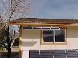
    Here the panel is mounted to a frame attached to the roof, well, under the roof. I didn't want to punch holes in the roof and possibly cause water leaks into the house. It's pretty clear from this photo that I was already planning for expansion. The empty area on the left would be filled soon enough.

    The Battery


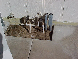
    [ photo of 12 volt 5 amp hour battery ]

    The battery is a standard "sealed" lead acid type. Sometimes referred to as VRLA (Valve Regulated Lead Acid) or Deep Cycle. Homes normally powered by solar electricity which have a battery bank use either Wet Cell or Sealed VRLA batteries. Both of these types are always Deep Cycle never "car" batteries. Keeping in line with home solar power, I chose the Sealed Deep Cycle battery for this experiment.

    Charging the battery


    It was a sunny morning in December 2002 and I was holding the little 5 amp hour sealed lead acid battery that I had purchased the day before. I was anxious to see the solar panel charging my new battery. So, at first I just propped up the panel inside one of the windows on the south side of the house to let the sun shine on it through the window glass. I hooked the solar panel in series with an ammeter on the positive wire to monitor current flow. I think I saw about 130 milliamps on the meter. Great! This is so cool, getting power from sunshine to charge the battery. OK, the battery is charging, so I left it like that and walked away for a few minutes.

    Oops! Wrong thing to do. When I returned, the battery was making a sound! The battery sounded like water simmering in a pan on the stove. Yikes! I disconnected the solar panel immediately. The sound stopped. The battery wasn't hot or leaking anything. I only left it hooked up to the solar panel for about 20 minutes.

    Important lesson learned: Don't connect solar panel directly to battery and leave it unattended!

    That single event has probably shortened the life and reduced the capacity of the battery.

    OK, some sort of automatic monitoring is needed for charging the battery. I knew that and was ready with an answer, a charge controller, but I didn't have one yet. No more charging from the solar panel until a proper charge controller is attached.

    Solar Charge Controller


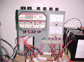
    [ photo of Morningstar Solar charge controller ]

    I chose the Morningstar ProStar-15 Charge Controller because the power handling capability is well suited to my small solar electric system, and it is regarded as highly reliable and good design from the reviews I've seen. It's capable of handling 15 amps total charge current into the battery, and 15 amps on the load side which is way more than I need right now. It will give me some room to add more solar panels and batteries to the system in the future, which is good.

    Here the charge controller is fully connected to into the solar electric system: solar panel, battery, load circuit  bedroom reading light. I have connected the load to the output of the charge controller instead of the battery directly. It will shut down the load if battery voltage drops below 11.4 volts, and reconnect power to the loads when the battery terminal voltage rises above 12.6 volts. A nice feature that will save the battery from being completely drained.

    Bedroom reading lamp


    [ photo of the first, original reading lamp ]

    The bedroom reading lamp shown here is pretty much the way I used it. A bare automotive 12 volt bulb soldered to some zip cord with a slide switch in-line for on off operation. I think I used a clamp or some tape to hold the lamp in position for reading. Primitive, yes, but it worked. My first foray into solar electricity.

    I was excited. Kinda cool laying there in bed reading by a light that came from sunlight earlier in the day. The local power company isn't reading the power used by this lamp on their kilowatt hour meter on the outside of my house. How cool is that? Yeah, this little step into solar electricity caused many thoughts to stir in my imagination.

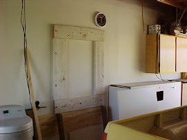
    Improvements to the system


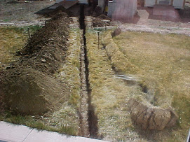
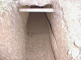
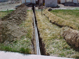
    Well, that was the start. It didn't take long before I was thinking about how to improve the safety and efficiency of operating the solar electric system. One of the first things I did was to move the battery and charge controller into the master bathroom, closer to where the solar panel wiring enters the house. The window seen in the photo behind the solar panel at the top of this post is the master bathroom. I drilled a tiny hole into the aluminum window frame to pass wires from the solar panel into the house. Yes I know, this doesn't meet code but it's just a temporary hook up for experimenting. So onward.

    I set the battery on the window sill. Attached some metal brackets to the back of the charge controller so I could attach it to the window sill with some clamps.


    [ photo of solar electric system on master bathroom window sill ]

    The analog meter in this photo is connected in series with the solar panel so I could monitor incoming current.  The charge controller can't read anything less than 200 milliamps. You can see the little plastic clamps on either side of the charge controller holding it to the window sill. The output connection to the reading lamp has a fairly long run of wires to get all the way to the headboard. It's about 15 feet from here to there.

    The automotive bare bulb pulls about 600 milliamps from the battery when it's on, which is a lot for a small light. So the next improvement is to find a useful reading lamp using less power. Here's my first answer to lowering the power.


    [ photo of better reading lamp ]

    A 12 volt fluorescent lamp pulls about 300 milliamps, that's half the current of the automotive bare bulb. And the light from this one is softer, whiter and diffused. Much nicer for reading. Things are looking up! If you look closely at the picture you'll see clamps at either end holding the lamp secure to the head board. Not pretty, but again, it works and after all this is an experiment.

    Battery monitoring


    The battery and charge controller are in the master bathroom while the reading lamp is in the bedroom, can't see them from the bedroom. The charge controller has a volt meter and LED's to show battery condition but, it would be nice to see something at the reading position. I would be able to see if I could read another page  or if I should turn the light off and go to sleep. Some time back I built a car battery voltage monitor using LED's. That would work here, it's 12 volts!


    [ photo of 12 volt car battery monitor ]

    All I had to do was attach two wires where the 12 volt power connects to the reading lamp. Cool! Now I have an indicator showing me battery voltage while in bed reading by the light. Well this is fun.

    How well is it working?


    I'm happy with the operation of everything connected to the system, but. Yeah, you knew there was going to be one of those. It seems there isn't much battery power at night to run the reading lamp. The "low battery" shutdown on the Charge Controller has shut off the reading lamp during use more than once. Annoying? Yes. I've seen the yellow and red LED's lighted on the Charge Controller fairly often telling me the battery is low.

    Well, research into proper charging profiles for lead acid batteries has shed light on the reasons for this happening. Listed here are important steps in caring for a deep cycle lead acid battery used in a solar home application.

    1. A battery should never be discharged more than 10% of its marked capacity in Amp Hours.
    2. A load on the battery should never exceed 10% of its marked capacity.
    3. Charge current into the battery should never exceed 20% of its marked capacity.
    4. A sealed VRLA battery should never be overcharged.

    When any of these are exceeded, even just briefly, the life and capacity of the battery is reduced. Normally they will live for 5 to 8 years, or even longer with great care.

    So, right off I managed to do #4 when I connected it directly to the solar panel and didn't monitor the voltage. My 5 amp hour battery is probably only worth 3 amp hours now, or even less!

    Let's take a close look at what we have here


    Loads:

    • Reading lamp, 300 ma, 1 hour per day, 0.3 ah/day
    • Charge controller, 20 ma, 24/7, 0.48 ah/day
    • LED voltage monitor, 30 ma, 24/7, 0.72 ah/day
    Total 1.5 ah/day (0.3 + 0.48 + 0.72 = 1.5)

    Charging:

    • Solar panel charging, 300 ma max
    • Prime Solar Window, 4 hr sunshine/day
    Total 1.2 ah/day (0.3 x 4 = 1.2), ideal conditions assuming 300 ma for 4 hours, can't happen, see below.

    Battery:

    • Sealed lead acid, 5 amp hour capacity (probably less now), 0.5 ah capacity solar home rating


    These figures show me that we've got a huge load on the little 5 amp hour battery, too much in fact.

    Daytime charging cycle is not enough to put back as much as we took out. The Prime Solar Window cited above is when the sun is high enough above the horizon to supply the maximum amount of energy into the solar panels. At other locations it can be 5.5 hours or even less than 2 hours, depending on your latitude above the equator. The calculation 300 ma for 4 hours cannot happen because the battery voltage will rise and the sun changes position during this time. When the voltage gets to about 14.4 volts the charge controller goes into regulation mode which holds the voltage constant by reducing current going into the battery. The result is that 300 ma won't hold the full 4 hours. Which means our calculation above is not correct in reality, but it does give us a rough idea of the charging capacity available during the day.

    The Charge Controller uses 20 milliamps around the clock and about 35 milliamps when it is actively charging the battery. So we have about 0.48 amp hours used up by the Charge Controller itself, leaving very little left for operating other loads (0.5 ah - 0.48 ah = 0.02 ah left for lights). Yikes!

    The LED voltage monitor uses more than the Charge Controller! It's using 30 milliamps around the clock which adds up to 0.72 ah. Again, yikes!

    Each one is too much load for the battery. Together they will kill the battery in a short time.

    Now that I have a better understanding of how to charge and how to use a sealed lead acid battery, I see why the system I've put together is not working right. I put too much load on the battery. Since I want to operate more than just the charge controller, it's time for a system upgrade.

    New solar panel


    [ photo of solar panel array, 2 panels ]

    three months later, March 2003...
    I knew designing the solar panel mount with an empty slot for another panel would come in handy, I just didn't know it would be this soon. Well, that's what experimenting is all about, learning from mistakes. The additional panel increases the current capability from 300 milliamps to 600 milliamps maximum, still below the recommended maximum 20% charge current, 1000 milliamps. Two 5 watt panels together make 10 watts total. That's going to help a lot.


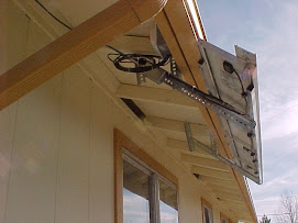
    [ photo of C-clamp holding solar panel mount to roof joist ]

    I removed the battery voltage monitoring LED display to reduce the overload condition. With these two improvements the battery fully recharges during the day and I get about 1/2 hour use of the reading lamp at night. There doesn't seem to be much power left in the battery at night and it's pretty low by morning from powering the Charge Controller all night long. I expected this because we're still overloading the battery.

    New battery

    one year later, December 2003...
    It is time to replace the abused 5 amp hour battery with a new one. I'll keep the original battery attached to the system because it seems to have some capacity left in it.


    [ photo of new 12 amp hour battery ]

    The new battery is rated at 12 amp hour capacity which is more than double the original 5 amp hour battery.  One tenth the marked capacity of this battery would be 1.2 amp hours. Our loads require 0.78 amp hours to operate so we should be OK now. Because the new battery will only see a proper charging profile from the Charge Controller it should last a long time and serve me well.

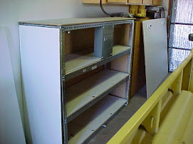
    Put everything into a proper enclosure


    At the time the 12 amp hour battery was added to the system I also mounted everything into a NEMA steel enclosure box purchased at a local home improvement center. I'm using this box for something other than its intended purpose, adding several fuses to the top of the box for circuit protection and tie points for external circuit connections. I added a couple large analog meters to show battery voltage and solar panel input current. The large square hole in the front is where a battery monitoring device was attached but I needed the  space for extra battery connections. It's a strong, heavy gauge, nicely painted metal box. Perfect!


    [ photo of NEMA steel enclosure ]

    The large terminal block had several high current pigtails attached, allowing me to connect external sealed lead acid batteries to the system. These batteries come from UPS units I no longer use. I just wanted to put them to use instead of just letting them sit idle, so here they are.


    [ photo of TriMetric battery monitor ]

    This is the Trimetric battery monitoring device I added to the system. I found out about this useful device while reading Home Power Magazine which is all about solar power use in the home. Very enlightening reading! You set up some parameters in the Trimetric describing the size of your battery (amp hours), the voltage, and the current sensing shunt you have attached to monitor incoming and outgoing current. Once this is done the device can tell you how much power has been used and how much is left. Very useful information which goes a long way to help you maintain a healthy battery bank.

    The Trimetric display gives you access to a lot of information about the condition and history of your battery. The information can help you to spot trouble so you can fix it before damaging your battery. For a solar power battery charging system, this is the most important piece of equipment you can have.

    How is it working now?


    Very well. The battery stays charged and in good condition. Once or twice during long, cold, cloudy winter days the battery didn't reach fully charged for several days. The charge controller's low battery shut down turned off the power to save the battery from being discharged too deeply. Those were some long, cold winter days where we had a thermal inversion: freezing fog on the ground in the valley where no sunshine gets through to the solar panels. Cold, but pretty, seeing frost collect on the trees, fences, telephone wires and solar panels!

    Knowledge is power


    All this time spent learning about battery charging and solar panels has taught me a great deal about the proper ways of designing and building a complete system.

    • Find the right size battery for the loads you intend to operate.

    The battery for my system has to operate a nighttime reading lamp for one hour per night and the Charge Controller 24/7, that's about 0.78 amp hours. Both batteries add up to 17 amp hours available for use but probably less due to the abused 5 ah battery. I purposely choose a battery too big so I could add some more loads for experimenting. Testing to see how much load is to little, and how much is too much.

    • Find the right size solar panel array to keep the batteries charged.

    The solar panels need to recharge the batteries with about one-and-one-half times the amount that was taken out of them. Two 5 watt panels will put out about 600 milliamps in full sunshine. 600 ma times 4 hours is 1.2 amp hours, which is pretty close to what we need. I won't let the battery get that low. Taking two days to bring the batteries up to a full charge isn't ideal, but it's not too harmful either. Just don't design a system where two days is the norm.

    • Use a high quality Charge Controller for charging the batteries.

    The Morningstar Pro-Star 15 is indeed a high quality, well designed Charge Controller. It is capable of handling much more power than my little system is using, allowing additional panels and batteries to be added at a later time.

    Charge Controller battery charging profile


    [ chart Sealed Lead Acid battery voltage charge profile ]

    This chart describes a normal "solar day" for the batteries, showing how battery terminal voltage changes during the day. Sunlight energizes the solar panels, in turn causing the Solar Charge Controller to charge the batteries in a very specific way. This curve represents an "ideal" charging profile on a sunny day. Some charge controllers do it very well. The Morningstar Pro-Star 15 in this system is one of those.

    Night
    This is typically when you use the batteries to provide light around the house, TV, radio and other uses.

    Bulk Charge
    When the sun comes up over the horizon in the morning the charging cycle begins. Direct current (DC) from the solar panels wakes up the Charge Controller which sends current into the batteries. Battery voltage starts rising slowly as the sun rises higher in the sky increasing the current. At this time the solar panels are producing as much power as they can.

    Absorb Charge
    When a set point voltage is reached, about 14.4 volts, the current begins to decrease which stops the voltage  from rising any further. During this time the batteries are absorbing, or accepting a full charge. This process removes sulfate from the lead plates and returns it into the battery acid solution.

    Float Charge
    When the current reaches a specific minimum value the battery terminal voltage is reduced. At this point the batteries are completely charged. While there is still sunshine available the Charge Controller will hold the batteries at an elevated voltage to simply keep them full. This voltage is about 13.7 volts at 70 F degrees. When the sun goes down the cycle starts all over again at night, discharging the batteries.

    Ongoing improvements

    8 months later, August 2004...
    The 12 amp hour battery is working very well for me but I want to increase the size of the system once again for some serious power capabilities. I want to operate 12 volt lights in the computer/workshop room at night.

    The new battery has 33 amp hour capacity. Adding it to the already existing 12 amp hour and 5 amp hour batteries makes the total 50 amp hour capacity. Do you see the difference here? I'm sizing the battery to the load, the preferred method of designing a system.

    I'm purposely not increasing the solar panel array size just yet. I want to see how this new ratio of solar panel size works with this size of battery bank. 10 watts of solar panel, and now 50 amp hours of battery capacity. This gives the system a 1:5 ratio, that's a wider spread than I originally figured would work. We'll see, it's still an experiment after all.


    [ photo of 33 amp hour battery ]

    2 1/2 years later, February 2007...
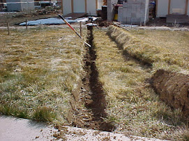
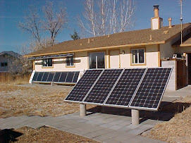
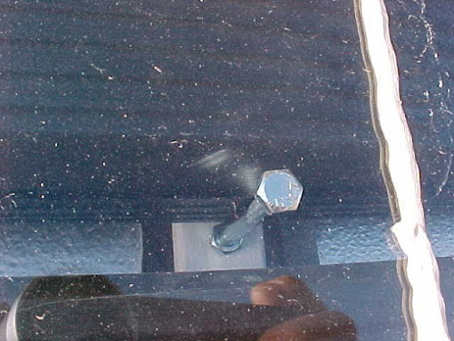
    I'm adding another 2 solar panels to the array to charge the batteries a little quicker. The solar panels are mounted in a new location. Stronger mounts, aesthetically pleasing to the neighbors (and me too), and it will allow future expansion. The first mounting for the two panels was just attached with C-clamps, this one uses 3/16 wood screws with pilot holes. Yeah, lots more professional.


    [ photo of 4 solar panel array ]

    I used B-Line angle steel to fabricate the mounting brackets for the solar panel array. That stuff is wonderful for building things. It's the adult sized Erector-Set, remember those?


    [ photo of solar panel array mounting brackets ]

    As I suspected the 1:5 ratio was a little too far to go. It kept the batteries charged pretty well but it was a struggle at times. Cloudy days would keep them from being fully charged. Several times in the 2 1/2 years it would take two days for the batteries to rise to the absorb voltage, only making it into the 13 volt range on some days.

    The additional solar panels will bring the system up to 20 watts total, 1.2 amps maximum charge current. This puts the ratio at 1:2.5 with 20 watts and 50 amp hours. A lower ratio like this will charge the batteries a little faster. On cloudy days it will bring the batteries to a higher charge level too.

    At this point the system ratio is below my gut feeling ratio of 1:3 being close to optimum. To adjust this a little  I'm going to add four 7 amp hour batteries to the system for a total capacity of 78 amp hours. That moves the ratio back to almost 1:4, where I lived with it that way for about three years from about 2003 to 2007. I was pretty much satisfied with the performance back then so adding these unused batteries to the system should be OK.

    78 amp hours of battery capacity is some serious power storage! I'm going to be able to use some of this power on my electronics workbench to do some real work. This is getting funner. Is that a real word?

    almost 2 years later, October 2008...
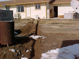
    At this point I have a large 12 volt system powering my home. The system is teaching me about wire size and voltage drop across terminals and connections. It's pretty amazing how easy it is for 12.7 volts at the battery to become 11 volts at the load when the circuit includes a few connections in between. The idea here is to start with a higher battery voltage. Then by the time the electricity arrives at the load the voltage drop will be a smaller percentage of the original battery terminal voltage, you get more power to the load.


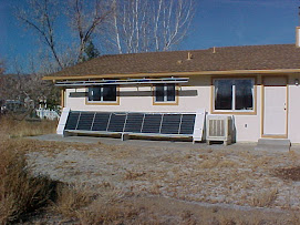
    [ photo of solar panels powering my home ]

    The system is working very well. In addition to using the 12 volt system for room lighting, I've been using it at my workbench to power electronic circuits I'm working on, charging 1.5 volt AA and AAA batteries, and all sorts of other things. Having a larger battery bank seems to keep a lot of power in reserve. Which brings me to the next adventure...

    Danger High Voltage


    It's time to try a 48 volt system. I've been thinking about energy storage and power. The relationship of voltage and power is interesting. All of the calculations for solar panel watts to battery amp hours that I have spoken of here are based on 12 volts. Those calculations don't work for 24 or 48 volt systems. So I want to see what higher voltage will do besides have less voltage drop on a long run of wire.


    [ photo of 12 solar panel array ]

    Solar panels for the 48 volt system are just an extension of the four 12 volt system panels you saw in the photo just above this one. Eight solar panels are used for the 48 volt system making the whole array twelve panels long. They are all the same Uni-Solar brand 5 watt, 12 volt 300 milliamp output.


    [ photo of 12 solar panel mounting brackets ]

    Four of these solar panels wired in series connection will give you 48 volts output at 300 milliamps. I want to build this system using four 33 amp hour batteries like the single one I added to the 12 volt system in 2003. It's a nice size and I have the perfect size shelf space just waiting for them. I need to make sure there is enough solar power to charge this battery bank. So, what have we got here...


    • Solar panels: 8 times 5 watt solar panels is 40 watts, 300 milliamps times 2 is 600 milliamps.
    • Batteries: 4 times 12 volt 33 amp hour wired in series, that's 48 volts at 33 amp hours. But this must be calculated in 12 volt terms, so that's 4 times 33 amp hours for a total 132 amp hours.
    • Charge rate: 132 amp hours divided by 40 (C/40), that's 3.3 or a ratio of 1:3.3. Great!


    We're right inside my gut feeling ratio at 1:3.3. The solar panels and battery choices have put us right in the middle of the sweet spot for building this system. I currently don't have any big plans for a load on this system, so I'll just take it slow and see what develops.

    An interesting application for the high voltage of this system presented itself. I have a collection of antique radios, some of which are battery powered. They usually take a low voltage high current A-battery to operate the filaments in the vacuum tubes, and a high voltage low current B-battery to operate the plates in the tubes. So... I connect a 1.5 volt AA cell for the filaments, and the 48 volts from the solar electric system for the plates. Yeah, I did it and it works great! Now this isn't really a "load" on the 33 amp hour batteries because these radios only draw 0.01 amps, that's 10 milliamps! One of these radios would never deplete the battery bank in this system. But it's kind of fun running the old vacuum tube radio with the 48 volt system.

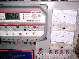
    Here is the 48 volt Morningstar Charge Controller mounted in a NEMA metal electrical box just like I did with the 12 volt system.


    [ photo of 48 volt Charge Controller NEMA box ]

    The LCD display in this photo is showing 52.6 volts and you can kind of see the same on the lower meter on the right. That's because the normal terminal voltage of a 12 volt battery is 12.7 volts when fully charged, usually higher than that when it's freshly charged. So the 52.6 divided by 4 is 13.15 volts. It's this high because when I took this picture the sun was just setting over the horizon after being held in float mode at 13.7 volts (54.8 volts) in the afternoon.

    Summary of things learned


    Each one of the systems described above was a methodical step in discovering how many watts of solar panel is required to charge a battery of a specific capacity. That is why I "lived with" each system for a period of time. I wanted to know how each design would work through the worst part of the year: Winter. When a system performed well in the Winter, it's a good design. On the other hand if it performed poorly in the Winter, something needs to change. Either reduce the load or increase solar panel size.

    Step 1
    5 watt solar panel, 5 amp hour battery. This is what I call a one-to-one ratio. This was my starting point. Unfortunately I "toasted" the battery right from the start, so this experiment didn't go as planned. My attempt to salvage this experiment led to the next step.

    Step 2
    10 watt solar panel, 5 amp hour battery. This is a two-to-one ratio. If 1:1 can't keep up with the loads then we'll just put more power into the battery with a larger solar panel array. What I took away from this setup is my gut feeling ratio that 2:1 of solar to battery is probably too high. The battery gets recharged OK but there isn't enough battery power to satisfy the load yet. This inspired the next step, bigger battery.

    Step 3
    10 watt solar panel, 12 amp hour battery. We're back to a one-to-one ratio. 12 amp hour battery is about two times the capacity I started out with. This system worked very well through the Winter season. So well in fact that it led me to the next experiment.

    Step 4
    10 watt solar panel, 33 amp hour battery added to the existing 12 amp hour gives us a total 45 amp hours. Now the ratio is one-to-four, 10 watts by 40 amp hours (rounded off). I lived with this system through 3 Winters and found the performance to be remarkably good. The battery capacity pulled me through some long cloudy spells without fully charging. My impression is the ratio of solar panel to amp hours needs to be a little closer than 1:4, maybe 1:3.

    Step 5
    20 watt solar panel, 12 ah + 33 ah + 7 ah + 7 ah + 7 ah + 7 ah = 73 amp hours. Here I added in the batteries from the UPS units. Now the ratio is about 1:3 (20 watts by 60 amp hours), 73 is half way between 1:3 and 1:4.

    Charge current into a sealed lead acid battery seems to work best when it is about 1/40th to 1/60th that of the marked battery capacity. That doesn't appear logical or intuitive. It just seems too low to be any good. But that's what my experiments seem to bear out.

    I have lived with the Step 5 setup now for 6 years. It works very well.

    Step 6
    The 48 volt system. 40 watt solar panel, 33 amp hour battery bank. I initially thought 1:3.3 ratio was right in the middle of the sweet spot. After 4 years of use, 2008 to 2012, I can tell you that I was right! This little system puts a good charge into the batteries even after I've used a fair amount of power out of them. Today I have a good size load for this system which is used daily. A 48 volt to 12 volt DC to DC converter which I use to power the DSL Router connected to my computer. The converter pulls about 270 milliamps at 48 volts while the Router pulls 400 milliamps at 12 volts from the converter. And, yes, I'm still powering the old vacuum tube radio on 48 volts too.


    2012 updates for both systems


    I am happy with both systems described here, but some new developments have presented themselves and I decided to make changes to both the 12 volt and 48 volt systems. Here's what happened.

    48 volt system
    January 2012 my boss and I buy a pallet of 200 watt 24 volt solar panels for a fraction of the price either of us paid for our originals several years ago. Long story short, I ended up with a broken solar panel from that purchase, completely shattered glass. In another blog post here you can read about how I repaired it, and how I rewired it for 48 volts. That broken solar panel now powers the 48 volt system. At about 125 watts, due to the damage, and 132 amp hours of batteries, that brings the ratio up to 1:1.

    12 volt system
    Since I removed the eight 5 watt solar panels from use on the 48 volt system to use the broken solar panel in their place, they would be sitting idle. I rewired them for 12 volts and added them to the original 4 panels on the 12 volt system. Now we have twelve 5 watt panels feeding the 12 volt system, 60 watts! With 60 watts of solar panels and 78 amp hours of batteries, that brings the ratio up to 1:1.

    We lost the original 5 amp hour battery in November 2012, it finally died. I noticed an unusual charging profile on the 12 volt system where the voltage would vary during the bulk charge phase. One-by-one I disconnected the batteries attached to the system. That's when I noticed the 5 amp hour battery felt a little warm. Warm! Yes, and looking at the case I could see a small bulge on one side. Yikes! As a result of these observations I removed it from service. The voltage measured about 10.5 volts. It's done. Gone. I put it in a safe place in case it decides to "GO" or leak or something. It will be recycled on my next trip to the battery store.

    That little 5 amp hour (abused) battery has been in service from December 2002 to November 2012, that's 10 years! I guess the sizzling sound from overcharging it in December 2002 reduced its capacity but that's a lot of years to be doing work without any complaints.

    Next up is the whole house solar electric system. I have learned a lot from the experiments carried out on this small system. I feel confident that I can design and build one to power my home. I plan to integrate electrical power from it one-step-at-a-time. In other words I'm not going to just plug in an arc welder, the dish washer and anything else electrical and just throw the switch. It too will be an experiment. More learning!


    Photo Gallery


    Gregg Scholfield    6-7-2013

    Friday, May 3, 2013

    Solar Heating Rev 3.0

    Here comes some serious solar heat


    I lived with solar heat from the Rev 2.0 system for two heating seasons, 2001 and 2002, and was not getting very warm on cold winter days. I experimented with varying the airflow and when the blower turns on and off. What I  found is that the system was working as well as could be expected. The maximum amount of heat it could supply was being harvested and delivered into the house. What is needed here is a larger heat collector.

    Rev 2.0 Solar Heat Collector


    [ photo of Rev 2.0 used for 2001 and 2002 heating seasons ]

    Rev 3.0 Solar Heat Collector


    [ photo of Rev 3.0 for 2003 and beyond ]

    This is the larger heat collector. You can see that I adopted the design of Rev 2.0 system by simply extending the down spouts from 10 feet to 20 feet in length. Effectively doubling the size of the solar collector  should increase the total amount of heat delivered into the house. I hope I'll be warmer on cold winter days. We'll see... The swamp cooler is also attached to the house at the same time, so no more rebuilding things when seasons change. There is a removable insulation partition inside the swamp cooler to close it off completely during the winter heating season.

    A less obvious thing you can't see in the photos above is where the cold house air enters the solar heat collector on the left end. I had to cut a new hole into the house to make that connection. I thought about this  for a long time. How best to do it. My final decision was to cut an opening at the end of the wall between floor joists. The result would be an opening 16 inches by 8 inches, more than was available for the Rev 2.0 crawl space vent design. What I didn't feel comfortable about was removing a section of the base plate at the end of the floor joists. Several years later there are no signs of a problem. I guess it is OK...


    [ photo of mid-section down spout support ]

    Two 10 foot down spouts joined end to end is a long span. All that weight will make the center joint sag and pull apart. Support is needed in the middle to hold the down spouts level for the whole 20 foot span. In the center of the solar heat collector is a steel frame with holes drilled in it where I attached 3 inch long 1/4 inch bolts. The bolts hold the down spouts level with no special attachment necessary because gravity holds them  resting against the steel frame and the bolt.


    [ photo of down spout end attachment ]

    On either end of the solar heater the down spouts are secured with a steel plate. Rectangle holes are cut into the plate which holds the spacing between each down spout. In this photo you can see caulking is used to seal the heat collector box from the heated air flow. The heat collector box is sealed air tight while cold house air is blown into the ends of the down spouts shown here. Heated air emerges from the other end of the down spout's 20 foot span.

    Some things I learned from the Rev 2.0 system


    [ photo of access door for furnace air filter ]
    • Furnace air filter
    Here you can see a little frame on the end of the solar heat collector in the lower left corner. It's an access door into the cold house air inlet. Behind the door is a standard size furnace air filter 14 by 20 inches. Previous designs didn't have an air filter. Inspection of the system at the end of the heating season revealed  evidence of dust collecting in the down spouts. Well, the first time I changed the filter after a heating season it was obvious how necessary an air filter is. Yuk! Really necessary.


    [ photo of cold house air entrance end ]
    • Access to internal workings
    You can see two aluminum straps with latches across the front of the box. These are easily removed to allow the cover to be lifted off to get inside for servicing. Rev 2.0 showed me how important it is to access the internal workings of the system. Rev 2.0 was held together with lots of wood screws...


    [ photo of aluminum strap with latch ]

    • Sun and weather destroy things
    The removable end covers have a layer of galvanized steel sheet metal tightly fitted. I carefully cut the sheet metal and formed it around the wood. When the fit was just right I soldered all the seams to completely shield it from the weather. Sun, rain and snow destroyed the Rev 2.0 covers in just two seasons! The value of learning from the previous experiment is priceless.


    [ photo of finished hot air plenum attached to swamp cooler ]

    • Switch between Winter heating and Summer cooling
    Rebuilding things isn't fun when the seasons change from heating to cooling. The solution was to modify the swamp cooler steel air plenum by cutting one side off. This opened a passage way for warm air to pass in front of the swamp cooler and into the house.


    [ photo of housing around swamp cooler plenum ]

    After modifying the swamp cooler plenum I built an insulated housing around the whole thing, seen above. Insulation is necessary for the Winter heating season to keep the heated air from being lost. The top of this section is covered with galvanized sheet steel soldered together and formed around the enclosure for a tight fit. Sun and water on this area will destroy wood within a couple years. Yes, that's experience talking... It was originally just painted wood, and it didn't last two years!

    How well does it work?


    Very well actually! There are still cold, cloudy Winter days when no heat is collected. When the sun does shine, however, it really warms the house. I use the term "warms" here as a "relative" measurement. What's that mean? Well, if the house is 45 F degrees in the morning, a sunny day with freezing temperatures outside will heat the house to around 60 F or 65 F degrees. So 60 F degrees is "warmer" than 45 F degrees, and it feels pretty nice too, when you remember how cold it was when the day started. And yes, if it remains cloudy all day the house remains at 45 F degrees. On those kind of days I'll use the wood heater or kerosene heater to add a little heat.

    During Spring and Fall seasons when the outdoor temperature is generally moderate around 35 F degrees to 50 F degrees, the solar heater warms the house to around 70 F or 75 F degrees. Sweet! So, yes, the solar heat collector is working very well for me.

    Ongoing improvements


    This Rev 3.0 system has been working well for me since I installed it in March 2003. Between then and December 2005 I used the blue squirrel cage blower described in my Rev 2.0 post. During this time I was exploring the possibility of powering the solar heat collector with solar electricity. I found that it is possible and probably a good idea to make it happen. On my electric bill I could see the affect of using the squirrel cage blower, it was a little higher during that time.

    In March 2004 I installed solar electric panels in my back yard. I had been working on a design for a solar heat fan controller system during this time. It would measure the temperature of the indoor air and measure the temperature of the solar heat collector air. When the solar heat collector air is warmer than the indoor air it would turn on the fans to move the heated air into the house. This way it should get the most heat into the house and use the least amount of power to do it.


    [ photo of solar heat collector fan controller circuit board ]


    [ photo of fan controller front panel ]

    This is the Fan Controller board I designed and built. It uses a Microchip PIC 16F628 processor chip. The job of this circuit is to open and close a duct work damper, turn the fans on and off with three speed settings. The duct work damper closes off the air path through the solar heat collector to prevent cold air from entering the house, back draft. This Fan Controller board communicates with a wall thermostat via RS485 serial network link.


    [ photo of wall thermostat Solar Controller ]

    The Solar Controller shown here is also my design using a Microchip 16F876 processor chip. It's job is to make all the decisions: when to turn the fans on and off, set fan speed, measure indoor air temperature, and get solar heat collector air temperature from yet another Microchip controller.

    Fan speed is slow when the difference between inside air temperature and the solar heat collector air temperature is about 6 F degrees. Medium speed at 12 F degrees and High speed when the temperature difference is above 18 F degrees. This controller is also connected to another via RS485 serial network which monitors the air temperature inside the solar heat collector.


    [ photo of solar heat collector air temperature monitor ]

    The Solar Temperature Monitor is shown here. Yes, I know, it's just sitting on a cabinet inside the house next to the warm air inlet. And it's just a modified "prototype" board from Micro Engineering Labs. The wires connect it to the RS485 serial network, 12 volt power, and the temperature sensor located inside the solar heat collector. I am planning on building a board specific to this purpose, enclosing it inside a metal box but just haven't got around to doing it. The saying, "If it ain't broke, don't fix it," comes to mind here. I've just been putting it off because "other" things are just more important. And so here it sits, operating perfectly for 8 years now!

    Let's take a look inside the finished system...


    Starting at the cold house air entrance we see there's a lot going on here. First a front view of the box with the cover removed.


    [ photo of cold house air entrance ]

    The front cover door is leaning against the house at the left. Inside the box on the lower half you can see 2 round black circles: these are the new 12 volt DC fans which replace the 120 VAC squirrel cage blower previously used in this location. Above those is a gray box with several flexible conduit cables attached. This is where the Solar Fan Controller is located.


    [ photo of Solar Fan Controller installed and operating ]

    LED indicators on the front panel show the current system status: NET on the left blink when transmit and receive network packets are being exchanged, FAN in the center show OFF (bottom) LOW, MED, HI (top), DAMP on the right shows the damper position OPEN or CLOSED. Fuses on the left are 5 volt for the logic board and 12 volt for the fans and damper.


    [ photo inside cold house air passage way ]

    Inside the access door on the left side of the box is where the furnace air filter is located. Both fans pull cold house air through the duct work behind the filter and force it into the solar heat collector's down spouts.


    [ photo of heated air output end box ]

    Heated air emerges at this end of the down spouts into this collector box. Notice the much thicker insulation on this end. That helps retain as much heat as possible before it enters the house. You can see some other things going on inside here too.


    [ photo of baffle and wall thermostat ]

    The diagonal piece of foam insulation is a baffle to prevent excessive air flow around the wall thermostat you can see at the top. The wall thermostat is used here as a "fail-safe" device. If the micro controllers should ever fail to run the fans when the sun is heating the down spouts, this thermostat will click-ON forcing the fans ON at full speed. That should prevent a melt-down of the solar heat collector by keeping air circulating.

    Again, yes, this is experience speaking from a previous "event" that did some damage. Foam insulation inside the down spout box partially melted from the heat! Ouch! The original software program I wrote for the wall thermostat in the hallway was at fault. It didn't convert temperature above 120 F degrees correctly, and just shut off the fans. Oops... Programming is now fixed, and this fail safe wall thermostat is now a permanent part of the system. The program and the fail-safe device have both been tested. They both passed. Now I feel better about the safe operation of the system. Lesson learned.


    [ photo close up of wall thermostat ]

    I am using the "air conditioner" contacts in the wall thermostat to close the fan circuit when the temperature here goes above 80 F degrees. You can see the dial setting red pointer on top. The bottom red pointer is ambient temperature and as you see it is off-the-scale above 100 F degrees. It's a good heating day!


    [ photo of solar heat collector temperature sensor clip ]

    This alligator clip holds the temperature sensor a short distance inside one of the down spouts. When the temperature of this sensor is 6 F degrees above room temperature inside the house, the damper opens and fans turn ON.


    [ photo of warm air entrance into the house ]

    Directly below the diagonal foam baffle is the opening where the warmed air passes into the house. Notice the liberal use of very thick foam insulation around the area. This is to keep as much heat in the air as possible.

    Why such expensive fans?


    [ photo close up of one of the 12 volt DC fans ]

    I did a great deal of searching to find the fans I chose to use here. Two very important factors had to be met for this purpose:
    1. Low power consumption.
    2. High enough CFM (Cubic Feet per Minute) air flow.
    These are two opposing features... You can have High air flow but you will have High power consumption. On the other hand you can have Low power consumption but you will have Low air flow. Papst brand 8 inch 12 volt DC fans move 235 CFM with only 1 amp draw from 12 volts DC. ONE AMP! Sweet. The closest competitor had the same air flow but uses 2.2 amps at 12 volts DC. Of course this efficiency comes at a premium price, $100 per fan. The 2.2 amp competitor could be had for $25 each.

    You must ask yourself this question, "Do I spend the money on high priced fans and build a smaller solar electric system, or do I build a large solar electric system and buy cheap fans?" Let's go through some numbers and see what it looks like.

    • $200 for two expensive fans
    • ...OR...
    • $2000 for a couple more solar panels
    • ...PLUS...
    • $1800 for batteries to handle the load of the cheap fans, total $2800

    It looks pretty clear to me that the expensive fans are a better choice. Things work a little differently when you want to use solar energy at your home instead of grid electricity.

    Solar energy requires a new way of thinking...


    This is the reality of solar energy with current technology. Solar energy works and is worth the effort however, the most important thing you will learn is conservation. You must use less than what you were while living on the grid. It's so easy to get comfortable connected to a seemingly "limitless supply" of electricity and natural gas. Making your own in your back yard is a limited supply. Your heat and electricity supply are now governed by the weather and your daily use of it. Your neighbors trees shading your solar panels and solar heat collector factor into this as well. You might have to wait for the next sunny day before you can do that load of laundry or vacuum the floors.

    Some of these things may not be appealing to you. I've struggled with all of them myself. They'll change your lifestyle, they have changed mine. Daily routines aren't so routine any more. When your home's power and heating is dependent on the weather, you will become acutely aware of what's going on outside. With the few years of experience living like this, it isn't so bad. Freedom from being tied to a utility for electricity or heat is a powerful feeling. I like the independence. I like being in control. Yes, this is worth the effort and lifestyle changes.

    Natural gas use since 2001


    The natural gas bill "event" February 2001 changed my life, for the better I think. My days and nights at home in Winter may be cooler and less comfortable than before the event but those aren't the only side effects. Here are two other side effects:


    [ photo of recent natural gas bill ]

    As you can see I'm no longer into "three digits" on my gas bill, saving some money in the process. The little graph on the gas bill kinda looks like the chart below. That's because natural gas only heats the hot water in my house. The dollar amount you see in the photo above is what I have been paying each month, every month since the "event" in 2001. Yes, over ten years now, less than $20 per month! Sweet!

    [ chart showing annual usage ]

    Clearly something is different starting in 2002. What you are looking at is hot water heater only from 2002 onward to today. The fiscal year 2013 is currently in progress, that's why it looks smaller that 2012. I think these two "side effects" of the lifestyle change are good ones.

    Modifications to the swamp cooler


    Having a large 1/3 hp AC electric motor pulling about 700 watts takes a toll on my solar electric system. There is also an AC water pump that sits in the bottom tray of the swamp cooler takes an additional 130 watts to operate. 830 watts. Running this on a 12 volt to 120 volt AC power inverter which is only 80% efficient means total power from the batteries is 830 x 1.2 = 996 watts total. Ouch!

    To remedy this situation I converted it over to use 12 volt fans and a 12 volt bilge pump. 12 volt fans pull about 30 watts directly from the batteries. 12 volt bilge pump pulls about 24 watts directly from the batteries. The new total is only 54 watts, and they don't use the 12 volt to 120 volt AC power inverter. Now that's a huge improvement and I'm saving some power for other things in my home.


    [ photo of original 1/3 hp driven blower ]

    The original squirrel cage blower, shown here removed from the swamp cooler, would move a large volume of air very quickly. With that much air moving it would cool the house down quickly. I would then switch the blower to a slower speed to keep from freezing myself in the middle of Summer. Anyway, it's big and uses a lot of power to run. More power than I wanted to use from the solar electric system powering my house.


    [ photo of swamp cooler with blower removed ]

    Lots of empty space inside now! The little red and white thing sitting on the bottom is the bilge pump.


    [ photo of 12 volt fan array inside swamp cooler ]

    The new 12 volt DC fans, 6 of them installed onto a board for easy removal. Each fan draws about 0.4 amp for a total of about 2.4 amps, 30 watts. These fans don't move the large volume of air that the original squirrel cage blower. Give it a little more time and the cooling effect through the house is the same. Are these fans noisy? No. The sound is a higher pitch whining but not loud at all. These were designed to be quiet. You have to strain to hear them running from the other end of the house. Nice cool breeze and using about about 950 watts less than before. That's cool!


    Photo Gallery


    Gregg Scholfield    5-3-2013