One Amp Battery Charger
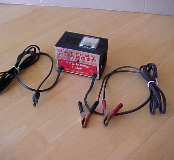
[ photo of battery charger, wide angle ]
When I purchased this little charger back in 1970 I didn't think I'd be writing about it today but here we are! Back then I was a lot younger, I had an old car for transportation, and it had an old battery. It didn't have a lot of cranking power when the weather turned cold, so I had to find a way to keep my wheels running. This little charger was the answer to my problems. But I digress.

[ photo close up of front panel ]
What brings us here today is a friend of mine, asking how to build a battery charger. He tells me that he has a couple of transformers and wonders what else is needed to make one. Well that's a pretty good starting point having a transformer, and there's not much more required to complete the job. A charger for a car battery can be really very simple, as long as there is a human to monitor the charging process. Cars and tractors have a Lead Acid wet cell battery, usually 6 or 12 volts.
We'll be looking at this Woodward-Schumacher Electric Corp. One Amp battery charger to get some ideas about what it takes to make one. I did a Google search and found Woodward-Schumacher is still in business designing and selling battery chargers. That is remarkable.
We'll be looking at this Woodward-Schumacher Electric Corp. One Amp battery charger to get some ideas about what it takes to make one. I did a Google search and found Woodward-Schumacher is still in business designing and selling battery chargers. That is remarkable.
Battery Charging Basics
To charge a Lead Acid battery is a fairly easy. DC current is driven into the battery from a controlled power source. Controlled to limit the current to a maximum level appropriate for the size of the battery, usually around 10% of the battery capacity. A 100 Amp Hour battery would be 10 Amps maximum, but following the battery manufacturer's recommendation is always the best option. This One Amp charger can charge a larger capacity battery, it will just take longer to get fully charged.
In the case of this One Amp charger the control is not very sophisticated or complex:

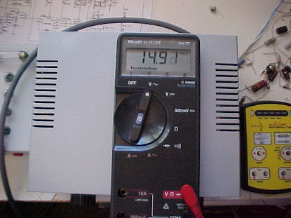
Checking the secondary AC voltage on the One Amp charger will show us about what we need to build our charger. Here's what I get with my Fluke 77 meter.

- It supplies limited power to the battery, 1 amp DC, due to the size of the transformer.
- The voltage output is limited by the transformer to about 15 volts.
Voltage of lead acid battery type for a car, engine cranking (intermittent high current demand).
- Dead 12.0 volts
- Operating 13.5 volts
- Charging 14.8 to 15.1 volts
- Dead 12.0 volts
- Operating 12.7 volts
- Charging 14.4 volts
Let's get on with the details of building a charger like this one using one of his transformers.
The Circuit
Here is a schematic diagram of what is inside the One Amp charger. The first thing that happens is the AC mains connect to a transformer which does three things:
The circuit also has a switch for selecting the correct voltage for the battery to be charged. AC voltage on the secondary of the transformer needs to be changed into DC (Direct Current) appropriate for charging a battery which is naturally DC itself. That job is performed by the Diode, only allowing current to pass through it in one direction. The direction of the arrow points to the Plus (+) side of the battery. Next there is a Thermal Breaker. This is a temperature controlled circuit breaker which will open and stop current flow to the battery if the current is too high. It is a safety device for protecting the battery and the charger from damage. After a short time period a Thermal Breaker will close the circuit and start current flowing into the battery again.
- Isolate the rest of the circuit from the power grid for your safety.
- Reduce the voltage to the level useful to the battery.
- Limit the amount of current going into the battery.
The circuit also has a switch for selecting the correct voltage for the battery to be charged. AC voltage on the secondary of the transformer needs to be changed into DC (Direct Current) appropriate for charging a battery which is naturally DC itself. That job is performed by the Diode, only allowing current to pass through it in one direction. The direction of the arrow points to the Plus (+) side of the battery. Next there is a Thermal Breaker. This is a temperature controlled circuit breaker which will open and stop current flow to the battery if the current is too high. It is a safety device for protecting the battery and the charger from damage. After a short time period a Thermal Breaker will close the circuit and start current flowing into the battery again.
[ schematic diagram ]
Transformer
Checking the secondary AC voltage on the One Amp charger will show us about what we need to build our charger. Here's what I get with my Fluke 77 meter.
[ photo of DMM reading 15.81v ]
The meter is reading 15.81 volts AC. I think the Fluke 77 actually reads AVERAGE voltage, not RMS. RMS readings are more accurate for measuring sine wave voltages, but this is close enough for us. The voltage shown here is reduced further by the drop across the rectifier changing the AC voltage to DC voltage for the battery.
Rectifier
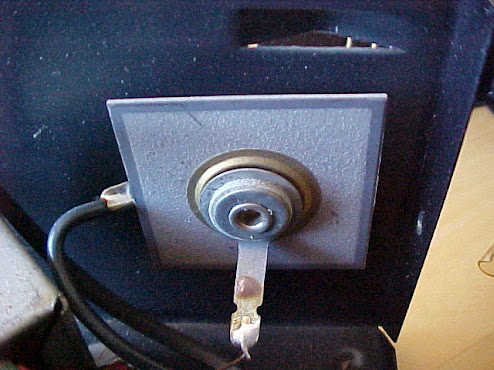
The One Amp charger uses an older style rectifier called a selenium rectifier. It may be old technology but they are still used in new equipment today. These are interesting devices and have some unique characteristics which make them particularly desirable for use in a battery charger. A Google search turned up an interesting article written by Rich Bonkowski describing the selenium rectifier in easy to understand terms. Here is what the selenium rectifier looks like in the One Amp charger. It's about 1 1/2 inch square.
[ photo of selenium rectifier ]
We subtract the voltage drop across the rectifier from the AC voltage reading on the secondary of the transformer which brings us closer to the voltage rating of the battery. Keep in mind the voltage output of the charger needs to be higher than the battery terminal voltage or there won't be current flow into the battery.
Here's what I measured for voltage drop across the selenium rectifier. Voltage vertical axis, current horizontal axis. Looks like the operating region will be around 1.50 volts drop from the selenium rectifier.
 [ chart selenium rectifier voltage drop vs current ]
I even made an attempt to take a picture of the waveform on the oscilloscope. I say attempt because it is an older analog Tektronix Scope with no photo capabilities at all. Here is what my old Sony camera did with it.


Here's what I measured for voltage drop across the selenium rectifier. Voltage vertical axis, current horizontal axis. Looks like the operating region will be around 1.50 volts drop from the selenium rectifier.
I connected a fairly dead battery to the One Amp charger and read about 0.8 Amps on the meter resulting in about 1.5 volts being dropped across the rectifier.
I even made an attempt to take a picture of the waveform on the oscilloscope. I say attempt because it is an older analog Tektronix Scope with no photo capabilities at all. Here is what my old Sony camera did with it.
[ photo of selenium rectifier AC waveform ]
It's hard to see any graticule markings in the picture, but the scale is 5 volts per div (vertical) and 5mS per div (horizontal), sync is set to the line frequency. It shows about 17.5 volts peak and this is with a 0.8 amp load. What this tells us is the battery voltage would have to rise to 17.5 volts for the current to drop to zero. Ouch!
This is why the charger MUST be monitored by a human during use!
For the voltage to go that high would require extraordinary circumstances.
Using Modern Parts
Rectifier
If you will be using a silicon diode rectifier in place of a selenium device there will be less voltage drop which means higher voltage to the battery. A silicon diode rectifier has a lower impedance than selenium resulting in higher current into the battery. Silicon diodes do not have the 'self healing' ability that selenium does which means if you connect to a very dead battery you might end up frying the silicon rectifier. Hence the need to have a fuse or some kind of safety limiting device to prevent this from happening.
Transformer
Modern transformers are OK to use, but a general purpose transformer may have a low impedance resulting in higher a current to the battery than your design. There are transformers designed for battery charger service which have built-in current limiting because of the air gaps within the iron core lamination. A low value high power resistor would remedy this, and also soften the surge capability of the silicon diode, however it will introduce a source of power loss and will generate heat. This is usually an equitable trade off in the design when the transformer isn't a perfect match.
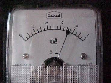
The Meter
The meter seen on the top of the One Amp charger is a modification I added to it myself not long after I purchased it. It's a standard 0-1 ma DC meter. I made a shunt out of a small coil of copper magnet wire so it would read 1 amp full scale. The shunt passes most of the current, leaving a small amount for the meter.
[ photo of meter from rear ]
[ photo close up of meter shunt wire winding ]
In the close up photo you can see the loop of wire above the coil. That is the half way point in the coil. Half of the coil is wound in one direction and the other half is wound in the opposite direction. The purpose of this is to make the coil nonmagnetic when current is passing through it. If the coil were wound in one direction only you would end up with an electromagnet which may affect the reading displayed on the meter. In any case, I have found the addition of the meter to be useful in helping determine if a battery is really dead or just needing to be topped off.
Using the One Amp Charger
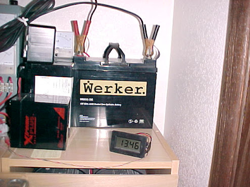
I attached the One Amp charger to a battery in my workshop and took some pictures of it in operation. The battery shown here is part of a bank of 12 volt AGM deep cycle batteries that I use for lights and other things. They are not automotive cranking type batteries but will serve as a load for this demonstration. You can see the battery clips attached to the top of this 33 amp hour battery.
[ photo of battery being charged with the One Amp Charger ]


[ photos showing charge current DC, battery voltage DC, transformer voltage AC, low battery ]

[ photos showing charge current DC, battery voltage DC, transformer voltage AC, high battery ]
[ photos showing charge current DC, battery voltage DC, transformer voltage AC, low battery ]
The readings here show the battery charge state is a little low at 12.61 volts, therefore is taking a little power from the charger. Charging current is 0.9 amps. Fluke meter shows AC volts from the transformer at about 14.01 volts, a little less than we saw above (15.81 volts) with no battery connected. This is because the battery is accepting current during the charge which loads down the transformer output voltage. All of these readings look normal and acceptable.
As the battery charges it's terminal voltage goes up and the readings look a little different. Charge current decreases, transformer AC voltage output increases. The battery is clearly accepting the charge and on its way to being restored to full capacity.
[ photos showing charge current DC, battery voltage DC, transformer voltage AC, high battery ]
Well that about raps it up. This little One Amp charger has served me well over the years. As we've seen it is a pretty simple circuit to build. The use of modern general purpose components need to be considered when building a charger like this one. Good luck with your design.
Gregg Scholfield 7-21-2012
EDIT: Updated 1-26-2013
Gregg Scholfield 7-21-2012
EDIT: Updated 1-26-2013
I have a manual Schumacher charger (model SE-82-6) with a switch for 6V@6A, 12V@2A and 12V@6A. Voltage output (avg meter) readings are about 7.9, 9.8 and 12.8 VDC. How is the current limited when the switch is in the 12V@2A position? Will the 9.8V output really charge a 12V lead-acid battery? TW
ReplyDeleteThe voltage measured out of a battery charger with no load (battery or resistor) connected to it can appear odd as you have seen. This voltage is usually pulsed rather than smooth DC, either at the line frequency of 60 or 30 HZ or some other. Your digital meter will try to average this signal on its DC setting, which is meaningless. Your best approach to finding out what the battery charger is really doing is to attach a battery with a current (Amp) meter in series with the output. This way the battery charger sees the load it was designed for and will operate normally. The series connected current (Amp) meter should be reading the actual current coming out of the battery charger and going into the battery.
ReplyDeleteThank you for your interest in my article. Gregg.
OK, your explanation is reasonable. I have access to a True RMS amp clamp that can show current flow direction. I will investigate further.
DeleteThe writeup you did was excellent, especially for somebody who doesn't have a lot of analog electrical experience, like me.
The diode explanation is very informative, I replaced the original button diodes in the SE-82-6 with discrete 50A silicon diodes even though they should never see that even for inrush (in theory anyway). I made sure they also have heat sinks. I appreciate you sharing your expertise. TW
Hi Greg wondering if you could point me in the right direction.
ReplyDeleteThis may sound a silly question but I do not have an electrical back gorund. We have an amp meter on our battery charger. On the back of the meter there is a coil which appears to be wound from a heavy kind of copper wire. Is this what you call the Shunt or am I totally on the wrong path?
Any advice appreciated
You are correct in your thinking, the coil of wire on the back of the meter is the shunt. Under "The Meter" heading in my post here there are 2 photos of the back of the meter. These photos clearly show the coil of wire attached to the meter terminals. This coil is the shunt. I hope this helps you out and thank you for your interest in my article.
DeleteThanks for the reply Gregg it is appreciated.
DeleteSo am I right in saying in basic terms that this is connected in live line between the charger and battery bank? Also should this have a fuse fitted?
Once again you are correct in your thinking, the coil of wire is connected "live" between the charger and battery. A fuse would be a very GOOD thing to have here in series with the battery. It will save things from getting destroyed and provide safety against fire if something should go wrong.
DeleteSince your battery charger is ONE AMP, a good choice of fuse size would be 2 amp slow blow type. A fast blow will work OK too, but the slow blow will have a better tolerance for a current surge when the charger is first turned on with a battery connected.
So when you mention series is this all in he same live line one after the other e.g live wire from charger goes into meter shunt, out of shunt into fuse at one side then out the other then connects to battery positive terminal?
DeleteOr should the fuse be before the shunt? Thanks again like i said before, i have little electrical knowledge but the way you explain things is straight forward.
DeleteThank you for the kind words about how I explain things. I try to do my best.
DeleteYour thoughts about how to connect the fuse is correct. Because the "live wire", "meter shunt", and "battery positive terminal" are all in a single straight line (series connections) you can put the fuse between any two of them. Choose what works best for you.
The thing we want to accomplish by installing a fuse is to protect the Battery Charger from the battery. The charger puts out ONE amp (I think, you didn't say). The battery on the other hand can put out HUNDREDS of amps depending on the size of the battery. Even a small one can put out a lot of amps for a fraction of a second - long enough to do some serious damage to whatever was connected.
How many AMPS does your battery charger put out?
Hello, on the front plate it has input 95-265VAC input 47-63Hz max input current 3A
DeleteDC output 24V/5ADC
Float 28.2V
Boost 29V
Would this mean the fuse would need to be 5Amp also?
DeleteThe tag on the batteries say: SAFT (Nicd) SMB30-2.
There looks to be 10 batteries although each battery looks to have 2 cells.
Thanks again
Interesting information, anonymous. It looks like your battery charger may be built for a 24 volt NiCd battery pack between 5 amp-hour and 20 amp-hour capacity.
ReplyDeleteYour description of the battery pack suggest it is a 24 volt pack, ie: 10 batteries with 2 cells each. If that is correct then: 1.2 volt cell (times) 20 cells (equals) 24 volts.
I did a Google search for "SMB30-2" and did not find any useful info, although I did find the "SAFT" company referred to many times.
Your question: Would this mean the fuse would need to be 5Amp also? Yes. 5 amp fast blow would be my choice.
Hello again Gregg, I can't thank you enough for your advice and help, it's interesting for me (novice) to learn the basics. If you dont mind, another query there is also a volt meter on the charger would i be correct in saying that this would be connected to the positive and negative from the battery some were in the wiring? Also would the wire that is attached to the + terminal on the back of the meter be fused as well? For your info our charger is a very old NIFE Jugner it has the year 1976 stamped on the details plate at the side. Just interested to find out what does what and why etc and your help is really appreciated.
DeleteThanks again
You're welcome, I'm glad that I was able to help you out with your questions.
DeleteThe question about the voltmeter being connected to the battery positive and negative somewhere in the wiring, yes it is connected that way.
And does the voltmeter need a fuse? No. The voltmeter is high impedance (very high resistance) so a fuse here would be of no use.
I just did a Google search NIFE Jugner and find that it looks like a German device, interesting, and 1976 wow!
Again, anonymous, happy to have been able to help you.
Yup 1976 and still going strong, built to last.
DeleteHave a happy new year when it comes Gregg, It's been a pleasure and I'm sure i'll have some more questions for you at some point haha.
Kind regards
Thank you for the kind words. It has been a pleasure talking about this stuff with you too. Happy New Year to you Anonymous.
DeleteHello again Gregg,How are you?
DeleteI'm back to pick you brains once again(if you don't mind? If you do then i'll understand lol)
We have been advised that our battery bank should have a disconnect device fitted such as fuses or an mccb. Once again I'm at a loss as to what is required. could you be so kind as to recommend what type of fuses or mccb I would need to fit? the battery type is Saft SBM30-2 i did a typo the last time sorry. The guy who told me I require a disconnect said that the batteries have a 22.2Amp discharge rate (all this is foreign to me).
Once again thank you so much for the help
Forgot to mention that we have no drawings not that that would make alot of sense to me lol
ReplyDeleteThank you for your interest in my article, Fedanng.
ReplyDelete